
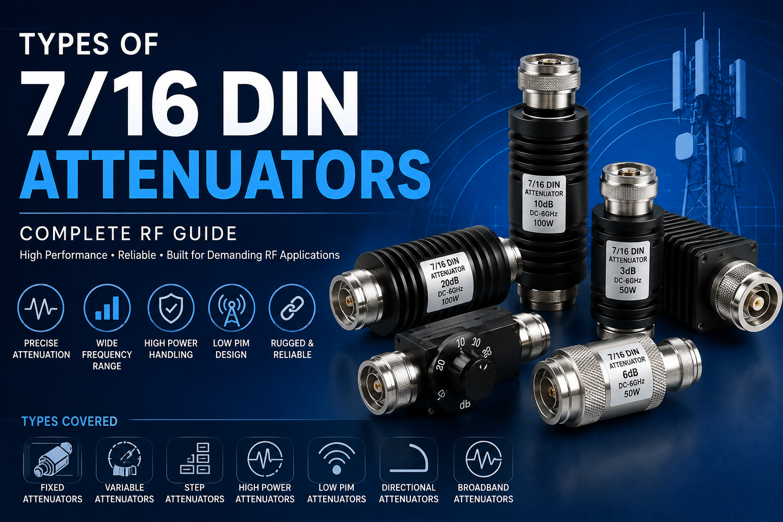
7/16 DIN attenuators are high-performance RF components designed to reduce signal power by a controlled amount while maintaining a stable impedance and reliable transmission path. They are widely used in cellular infrastructure, distributed antenna systems, RF distribution networks, broadcast systems, laboratory testing, wireless communication equipment, and high-power RF applications.
The 7/16 DIN interface is a rugged 50-ohm coaxial RF connector designed for demanding communication environments. Its robust mechanical construction, high-power capability, and suitability for low passive intermodulation applications make it particularly valuable in modern cellular and telecom infrastructure. The connector is standardized under IEC 61169-4.
A 7/16 DIN attenuator combines this rugged connector interface with an attenuation network that reduces RF signal amplitude. Depending on the design, a 7/16 DIN attenuator may provide a fixed attenuation value, adjustable attenuation, stepped attenuation, directional operation, or specialized high-power and low-PIM performance.
Understanding the different types of 7/16 DIN attenuators is essential when selecting an RF component for a base station, antenna system, DAS installation, RF test setup, or high-power transmission application.
What Is a 7/16 DIN Attenuator?
A 7/16 DIN attenuator is a passive RF device that reduces the power level of an RF signal while providing a controlled 50-ohm transmission path.
The amount of signal reduction is expressed in decibels (dB). Common attenuation values can include 1 dB, 3 dB, 5 dB, 6 dB, 10 dB, 20 dB, 30 dB, and higher values, depending on the product design.
For example, a 10 dB attenuator reduces the signal power delivered to the next stage by a factor of 10 under an ideal matched system.
7/16 DIN attenuators can be used to:
- Reduce excessive RF signal power
- Protect sensitive RF equipment
- Control signal levels
- Improve system matching
- Reduce the impact of impedance mismatch
- Extend the measurement range of RF instruments
- Simulate cable or propagation loss
- Support antenna and transmitter testing
- Control power distribution in RF networks
Fixed RF attenuators are commonly used for known and permanent signal reduction, while variable and step attenuators provide adjustable signal-level control.
Why Use a 7/16 DIN Attenuator?
The connector interface is an important reason for selecting a 7/16 DIN attenuator instead of a smaller RF connector.
7/16 DIN connectors are designed for high-power RF communication applications and are widely used in cellular base stations and antenna systems. Their rugged construction also makes them suitable for installations where mechanical strength and reliable RF connections are important.
Major advantages include:
- High mechanical durability
- 50-ohm impedance
- High RF power capability
- Suitable for telecom infrastructure
- Good RF performance
- Availability in male and female configurations
- Compatibility with large coaxial cables
- Suitability for low-PIM applications
- Reliable threaded coupling
Main Types of 7/16 DIN Attenuators
The major types of 7/16 DIN attenuators can be classified according to attenuation control, construction, power capability, directionality, and application.
The most common categories include:
- Fixed 7/16 DIN Attenuators
- Variable 7/16 DIN Attenuators
- Step 7/16 DIN Attenuators
- High-Power 7/16 DIN Attenuators
- Low-PIM 7/16 DIN Attenuators
- Directional 7/16 DIN Attenuators
- Broadband 7/16 DIN Attenuators
- Termination-Type Attenuators
- Male-to-Female 7/16 DIN Attenuators
- Female-to-Female 7/16 DIN Attenuators
- Male-to-Male 7/16 DIN Attenuators
- Custom 7/16 DIN Attenuators
1. Fixed 7/16 DIN Attenuators
A fixed 7/16 DIN attenuator provides a predetermined attenuation value that remains constant during normal operation.
This is one of the most widely used types of RF attenuator because it is simple, reliable, compact, and does not require mechanical adjustment or electronic control.
Typical attenuation values may include:
- 1 dB
- 2 dB
- 3 dB
- 5 dB
- 6 dB
- 10 dB
- 15 dB
- 20 dB
- 30 dB
- 40 dB
- 50 dB
- 60 dB
The exact values depend on the manufacturer, frequency range, power rating, and mechanical configuration.
Applications of Fixed 7/16 DIN Attenuators
Fixed 7/16 DIN attenuators are commonly used in:
- Cellular base stations
- RF distribution systems
- DAS networks
- Antenna systems
- RF power amplifiers
- Broadcast infrastructure
- Wireless communication systems
- RF test equipment
- Laboratory measurement systems
Advantages
- Simple design
- High reliability
- No moving components
- Stable attenuation
- Repeatable RF performance
- Suitable for permanent installations
- Available in high-power configurations
2. Variable 7/16 DIN Attenuators
A variable 7/16 DIN attenuator allows the user to change the amount of signal attenuation over a specified range.
Instead of providing one fixed value, a variable attenuator may allow continuous adjustment using a mechanical control mechanism.
Variable attenuators are particularly useful during RF testing, calibration, system development, and field optimization.
Applications
- RF laboratories
- Antenna testing
- Transmitter testing
- Receiver testing
- RF calibration
- Wireless network commissioning
- Research and development
Benefits
- Adjustable signal level
- Flexible RF testing
- Reduced requirement for multiple fixed attenuators
- Useful for system optimization
- Suitable for controlled signal-level experiments
Continuously variable attenuators are especially useful when smooth adjustment is required rather than predefined attenuation states.
3. Step 7/16 DIN Attenuators
A step attenuator provides attenuation in predefined increments.
Instead of continuously rotating through every possible value, the user selects specific attenuation steps.
For example, a step attenuator may provide settings such as:
- 0 dB
- 1 dB
- 2 dB
- 4 dB
- 8 dB
- 10 dB
- 20 dB
Multiple attenuation sections can be combined to achieve different total attenuation levels.
Advantages of Step Attenuators
- Repeatable attenuation
- Precise signal control
- Easy calibration
- Defined attenuation states
- Suitable for automated testing
- Useful in RF measurement systems
Step attenuators can be especially useful where repeatability is more important than continuously adjustable control.
4. High-Power 7/16 DIN Attenuators
High-power 7/16 DIN attenuators are designed to dissipate significant RF energy while maintaining acceptable RF and thermal performance.
They are commonly used in high-power transmitter chains, cellular infrastructure, RF power amplifier testing, and antenna systems.
A high-power attenuator may use a larger body or integrated heat-dissipation structure to manage the heat generated by the attenuation network.
For example, commercially available 7/16 DIN fixed attenuators can be designed for substantial power levels and may incorporate heatsink-style construction.
Important Specifications
When selecting a high-power 7/16 DIN attenuator, check:
- Average power rating
- Peak power rating
- Frequency range
- Attenuation value
- VSWR
- Insertion loss
- Operating temperature
- Thermal design
- Connector configuration
Never select a high-power attenuator based only on its connector type. The actual power rating and thermal conditions must match the application.
5. Low-PIM 7/16 DIN Attenuators
Low-PIM attenuators are designed for RF systems where passive intermodulation must be minimized.
PIM is particularly important in cellular communication systems because unwanted intermodulation products can interfere with receive bands and degrade network performance.
7/16 DIN connectors are widely associated with high-power cellular infrastructure and applications where low passive intermodulation is important.
Applications
Low-PIM 7/16 DIN attenuators are commonly considered for:
- Cellular base stations
- DAS
- Distributed antenna systems
- Mobile communication infrastructure
- Multi-carrier RF systems
- Outdoor telecom installations
- Antenna feeder networks
Low-PIM Design Considerations
Low-PIM performance can depend on:
- Connector materials
- Contact geometry
- Surface finish
- Mechanical stability
- RF current distribution
- Manufacturing quality
- Cable and connector interface
- Assembly cleanliness
A low-PIM attenuator should therefore be evaluated as part of the complete RF path rather than as an isolated component.
6. Directional 7/16 DIN Attenuators
A directional attenuator is designed to provide attenuation characteristics that depend on signal direction or to integrate directional coupling and measurement functionality.
Directional RF components can be useful when monitoring forward and reflected power or managing RF signals in transmission systems.
Applications
- RF power monitoring
- Base station testing
- Transmitter systems
- Antenna testing
- RF measurement
- High-power communication systems
Directional behavior should always be checked against the manufacturer’s specifications because attenuation, coupling, directivity, and return loss can vary significantly by design.
7. Broadband 7/16 DIN Attenuators
A broadband 7/16 DIN attenuator is designed to provide useful attenuation across a wide frequency range rather than being optimized for only a narrow frequency band.
Broadband attenuators are useful in RF systems that operate across multiple frequencies or where the same test equipment must support different wireless bands.
Applications
- RF laboratories
- Telecom testing
- Multi-band cellular systems
- Antenna measurements
- RF distribution
- Production testing
The most important parameter is attenuation flatness across the intended operating frequency range.
8. Termination-Type 7/16 DIN Attenuators
Some RF systems use attenuating loads that combine signal reduction with power dissipation.
These components can be useful when a signal must be reduced and the resulting RF energy must be safely dissipated.
They should not be confused with a standard 7/16 DIN termination or dummy load. A termination primarily absorbs RF power to provide a controlled load, whereas an attenuator passes the signal through while reducing its level.
Applications
- RF testing
- Transmitter development
- Power measurement
- Load testing
- RF laboratory systems
9. Male-to-Female 7/16 DIN Attenuators
Male-to-female 7/16 DIN attenuators have a male connector on one side and a female connector on the other.
This configuration is commonly used for inline installation between two RF interfaces.
Benefits
- Easy integration
- Direct equipment connection
- Compact installation
- Suitable for coaxial RF systems
Connector gender should always be checked before ordering an attenuator to ensure compatibility with the existing equipment and cable assembly.
10. Female-to-Female 7/16 DIN Attenuators
Female-to-female attenuators provide female interfaces on both ends.
They may be useful when connecting male-ended RF components while maintaining a specified attenuation value.
Applications
- RF test setups
- Cable assemblies
- RF distribution networks
- Equipment interconnection
- Antenna systems
11. Male-to-Male 7/16 DIN Attenuators
Male-to-male attenuators provide male connectors on both sides.
They are used where two female RF interfaces need to be interconnected while introducing a controlled amount of attenuation.
Before selecting this configuration, verify connector dimensions, gender, coupling requirements, frequency range, and power rating.
12. Custom 7/16 DIN Attenuators
Custom 7/16 DIN attenuators can be designed or configured according to application-specific requirements.
Customization may involve:
- Attenuation value
- Frequency range
- Power rating
- Connector gender
- Connector orientation
- Body dimensions
- Thermal management
- Low-PIM requirements
- Environmental protection
- Special mounting requirements
Custom RF attenuators are useful when standard catalog products cannot satisfy the required electrical or mechanical specifications.
Fixed vs Variable vs Step 7/16 DIN Attenuators
| Feature | Fixed | Variable | Step |
|---|---|---|---|
| Attenuation | Preset | Adjustable | Predefined steps |
| Adjustment | No | Continuous | Discrete |
| Repeatability | Excellent | Depends on mechanism | Excellent |
| Mechanical Parts | Minimal | Usually present | Usually present |
| Testing | Good | Excellent | Excellent |
| Calibration | Simple | Flexible | Highly repeatable |
| Permanent Installation | Excellent | Moderate | Good |
| Automated Testing | Limited | Possible | Excellent |
| Typical Use | Signal padding | RF tuning | Precision testing |
The choice depends on whether the application prioritizes simplicity, continuous adjustment, or repeatable attenuation states.
7/16 DIN Attenuator Attenuation Values
Attenuation is measured in decibels.
Common attenuation values include:
- 1 dB
- 2 dB
- 3 dB
- 5 dB
- 6 dB
- 10 dB
- 15 dB
- 20 dB
- 30 dB
- 40 dB
- 50 dB
- 60 dB
The appropriate attenuation value depends on the signal level, system architecture, receiver input requirements, and desired power level.
For example, a 10 dB attenuator reduces power by a factor of 10 in an ideal matched system, while a 20 dB attenuator reduces power by a factor of 100.
Understanding 7/16 DIN Attenuator Power Rating
Power handling is one of the most important specifications when selecting a 7/16 DIN attenuator.
The power rating indicates how much RF power the attenuator can dissipate without exceeding its thermal or electrical limits.
Power ratings can be specified as:
- Average power
- Continuous-wave power
- Peak power
- Pulsed power
A high-power RF attenuator must be selected based on the actual operating conditions, including duty cycle, ambient temperature, ventilation, mounting, and RF frequency.
7/16 DIN Attenuator Frequency Range
Frequency range defines the RF spectrum over which the attenuator is specified to operate.
The attenuation value may not remain perfectly constant across the entire frequency range.
Important parameters include:
- Frequency range
- Attenuation flatness
- VSWR
- Return loss
- Insertion loss
- Power handling
An attenuator should always be selected with a frequency range that covers the complete operating band of the RF system.
7/16 DIN Attenuator VSWR
VSWR, or Voltage Standing Wave Ratio, indicates how well the attenuator is impedance matched to the RF system.
A lower VSWR generally indicates better matching and lower signal reflection.
Good impedance matching is particularly important in RF systems because reflections can affect:
- Transmitter performance
- Receiver sensitivity
- Power transfer
- Measurement accuracy
- System stability
Attenuators are often used not only to reduce signal level but also to improve the impedance environment seen by adjacent RF components.
7/16 DIN Attenuator Return Loss
Return loss measures the amount of RF power reflected back toward the source due to impedance mismatch.
Higher return loss generally indicates better impedance matching.
When evaluating a 7/16 DIN attenuator, return loss should be considered alongside VSWR and insertion loss.
7/16 DIN Attenuator Insertion Loss
Insertion loss describes the loss introduced by an RF component when it is inserted into a transmission path.
For an attenuator, the specified attenuation is intentional, while additional insertion loss can result from the internal RF structure and connectors.
A high-quality attenuator should provide predictable attenuation with stable RF performance across its specified frequency range.
7/16 DIN Attenuator Connectors
The 7/16 DIN connector is a threaded RF interface designed for robust coaxial connections.
Connector configurations can include:
- 7/16 DIN male
- 7/16 DIN female
- Male-to-female
- Female-to-female
- Male-to-male
- Bulkhead configurations
- Panel-mount configurations
The correct connector configuration is important for mechanical compatibility and reliable installation.
7/16 DIN Attenuators in Cellular Networks
Cellular infrastructure is one of the most important applications for 7/16 DIN attenuators.
They can be used in:
- Base station RF paths
- Antenna feeder systems
- DAS networks
- RF combiners
- RF splitters
- Power distribution systems
- Antenna test systems
Attenuators help control signal levels and can be used to balance RF paths within complex communication infrastructure.
7/16 DIN Attenuators for DAS
Distributed Antenna Systems use multiple antennas and RF distribution components to provide wireless coverage throughout buildings, tunnels, transportation facilities, campuses, and other challenging environments.
7/16 DIN attenuators can help control the power delivered to different branches of a DAS.
Proper attenuation can help balance RF levels between different paths and reduce excessive signal levels at specific points in the network.
7/16 DIN Attenuators for RF Testing
RF laboratories use attenuators to control the signal level delivered between test equipment and devices under test.
Typical applications include:
- Signal generator testing
- Spectrum analyzer protection
- Receiver sensitivity testing
- Transmitter characterization
- Antenna testing
- Cable testing
- RF calibration
- Power amplifier testing
An RF attenuator can also help establish a known loss between instruments during measurements.
7/16 DIN Attenuators for Base Stations
Base stations often operate with relatively high RF power levels and require mechanically robust interconnects.
7/16 DIN attenuators can be used for:
- RF power adjustment
- Signal balancing
- Test access
- Equipment protection
- Antenna path testing
- Commissioning
- Maintenance
High-power and low-PIM characteristics may be particularly important in cellular base station applications.
How to Select the Right 7/16 DIN Attenuator
Selecting the correct attenuator requires evaluating the complete RF system.
1. Determine the Required Attenuation
Identify the amount of signal reduction required in dB.
2. Check the Frequency
Ensure the attenuator covers the entire operating frequency range.
3. Calculate Required Power Handling
Determine the maximum continuous and peak RF power that the attenuator must handle.
4. Check VSWR
Select an attenuator with suitable impedance matching for the application.
5. Consider PIM Requirements
For cellular and multi-carrier systems, low-PIM performance may be an important selection criterion.
6. Select the Correct Connector Configuration
Verify whether the application requires 7/16 DIN male, female, male-to-female, female-to-female, or another configuration.
7. Select Fixed or Adjustable Operation
Use fixed attenuation when the required signal reduction is known and permanent.
Use variable attenuation when continuous adjustment is required.
Use step attenuation when repeatable predefined attenuation values are needed.
8. Consider Environmental Conditions
For outdoor telecom installations, evaluate:
- Operating temperature
- Humidity
- Corrosion resistance
- Weather protection
- Mechanical durability
- UV exposure
- Mounting requirements
Common 7/16 DIN Attenuator Selection Mistakes
Choosing the Wrong Power Rating
A component with an inadequate power rating can overheat or fail.
Ignoring Frequency
An attenuator may work at one frequency range but fail to meet its specified performance at another.
Selecting Gain Instead of Attenuation
Attenuators reduce RF power. The required attenuation value should be calculated based on the desired signal level.
Ignoring PIM
In cellular networks, an attenuator that does not meet the required PIM performance may negatively affect overall system performance.
Using the Wrong Connector Gender
Mechanical incompatibility can prevent proper installation or require additional adapters.
Ignoring Thermal Conditions
High-power attenuators generate heat. Ambient temperature and airflow can influence their practical power handling.
7/16 DIN Attenuator Maintenance
Although fixed attenuators are generally low-maintenance components, proper installation and inspection can improve system reliability.
Recommended practices include:
- Inspect connector surfaces
- Keep mating interfaces clean
- Avoid excessive mechanical force
- Use the correct coupling procedure
- Check cable routing
- Inspect for corrosion
- Verify RF performance during maintenance
- Monitor abnormal temperature rise
- Avoid exceeding rated power
In outdoor installations, environmental inspection is especially important.
Testing 7/16 DIN Attenuators
RF attenuators can be evaluated using appropriate test equipment such as:
- Vector Network Analyzers
- Signal generators
- Spectrum analyzers
- RF power meters
- Return-loss measurement systems
- PIM test equipment
Important measurements may include:
- Insertion loss
- Attenuation accuracy
- Return loss
- VSWR
- PIM
- Frequency response
- Power handling
- Temperature performance
Key Specifications of a 7/16 DIN Attenuator
| Specification | Importance |
|---|---|
| Connector Type | Mechanical compatibility |
| Impedance | Usually 50 ohms |
| Frequency Range | Defines usable RF spectrum |
| Attenuation | Defines signal reduction |
| Power Rating | Defines maximum RF handling |
| VSWR | Indicates impedance matching |
| Return Loss | Indicates reflected power |
| PIM | Important for cellular systems |
| Insertion Loss | Defines additional transmission loss |
| Operating Temperature | Environmental suitability |
| Connector Gender | Installation compatibility |
| Mounting | Mechanical integration |
Applications of 7/16 DIN Attenuators
7/16 DIN attenuators are used across several RF industries.
Telecommunications
Used in cellular base stations, RF distribution, antenna feeder systems, and wireless communication infrastructure.
Distributed Antenna Systems
Used for RF power balancing between multiple antenna branches.
Broadcast
Used in RF transmission and signal distribution systems.
Test and Measurement
Used for controlling signal levels and protecting sensitive test equipment.
Aerospace and Defense
Specialized RF attenuator configurations can be used in high-performance communication and RF test environments.
Industrial RF Systems
Used in high-power RF systems, wireless infrastructure, and specialized communication equipment.
Research and Development
Used in RF laboratories for signal-level adjustment and system characterization.
Benefits of 7/16 DIN Attenuators
The main benefits include:
- Robust RF interface
- High-power capability
- Controlled signal reduction
- 50-ohm impedance
- Reliable mechanical connection
- Suitable for telecom infrastructure
- Availability in multiple attenuation values
- Fixed and adjustable options
- Potential low-PIM configurations
- Suitable for outdoor and demanding environments
7/16 DIN Attenuator vs N-Type Attenuator
Both 7/16 DIN and N-Type connectors are used in RF systems, but their mechanical and performance characteristics differ.
7/16 DIN is particularly common in high-power cellular infrastructure, while N-Type connectors are widely used across general RF, wireless, instrumentation, and antenna applications.
The appropriate connector should be selected based on:
- Power level
- Frequency
- PIM requirements
- Mechanical environment
- Cable type
- Existing equipment interfaces
7/16 DIN Attenuator vs SMA Attenuator
SMA connectors are much smaller than 7/16 DIN connectors and are commonly used in compact RF and microwave equipment.
7/16 DIN is generally preferred for larger, ruggedized, high-power telecom infrastructure, whereas SMA is frequently selected for laboratory, PCB, instrumentation, and compact RF applications.
The connector should always be chosen based on the complete system rather than connector size alone.
Future Trends in 7/16 DIN Attenuators
The continuing expansion of cellular networks, private 5G, distributed antenna systems, and high-capacity wireless infrastructure is increasing the importance of reliable RF passive components.
Future development areas include:
- Higher-power attenuation
- Improved low-PIM performance
- Wider frequency coverage
- Better thermal management
- More compact high-power designs
- Improved environmental protection
- Enhanced mechanical durability
- Specialized RF monitoring configurations
- Custom telecom-grade solutions
As wireless networks become more complex, RF passive components must provide stable performance across multiple carriers, frequencies, and power levels.
Conclusion
7/16 DIN attenuators are important passive RF components for controlling signal levels in high-power and demanding wireless communication systems.
The main types include fixed, variable, step, high-power, low-PIM, directional, broadband, termination-type, and custom 7/16 DIN attenuators. Each type serves a different purpose, from simple permanent signal reduction to precise RF testing and high-power cellular infrastructure.
When selecting a 7/16 DIN attenuator, engineers should consider attenuation value, frequency range, power handling, VSWR, return loss, PIM performance, connector gender, environmental conditions, and installation requirements.
For cellular base stations, DAS, antenna systems, RF distribution networks, and high-power telecom infrastructure, selecting a properly specified 7/16 DIN attenuator can help maintain controlled signal levels, reliable RF performance, and long-term system stability.
Frequently Asked Questions (FAQs)
1. What is a 7/16 DIN attenuator?
A 7/16 DIN attenuator is a 50-ohm RF component that reduces the power level of an RF signal by a specified amount while maintaining a controlled coaxial transmission path.
2. What are the main types of 7/16 DIN attenuators?
The main types include fixed, variable, step, high-power, low-PIM, directional, broadband, termination-type, and custom 7/16 DIN attenuators.
3. What is a fixed 7/16 DIN attenuator?
A fixed 7/16 DIN attenuator provides a predetermined attenuation value that remains constant during operation.
4. What is a variable 7/16 DIN attenuator?
A variable 7/16 DIN attenuator allows the attenuation level to be adjusted over a specified range, making it useful for RF testing, calibration, and system optimization.
5. What is a step 7/16 DIN attenuator?
A step attenuator provides predefined attenuation levels that can be selected in specific increments. It is useful when repeatable signal-level control is required.
6. Why are 7/16 DIN attenuators used in cellular networks?
They are used because the 7/16 DIN interface is rugged and suitable for high-power RF infrastructure. Attenuators help control RF power levels in base stations, DAS networks, antenna systems, and RF distribution paths.
7. What is a low-PIM 7/16 DIN attenuator?
A low-PIM 7/16 DIN attenuator is designed to minimize passive intermodulation products, making it suitable for multi-carrier cellular and wireless communication systems.
8. What does 7/16 DIN mean?
7/16 DIN refers to a rugged threaded coaxial RF connector family commonly used in high-power communication infrastructure. The interface is associated with a 50-ohm RF system and is standardized under IEC 61169-4.
9. What attenuation values are available for 7/16 DIN attenuators?
Depending on the manufacturer and application, common values include 1 dB, 3 dB, 5 dB, 6 dB, 10 dB, 20 dB, 30 dB, 40 dB, and higher attenuation values.
10. How do I choose a 7/16 DIN attenuator?
Consider the required attenuation, frequency range, RF power, VSWR, PIM requirements, connector gender, environmental conditions, and whether fixed, variable, or step adjustment is required.
11. Can a 7/16 DIN attenuator handle high RF power?
Yes. High-power 7/16 DIN attenuators are specifically designed for demanding RF applications. However, the exact power rating depends on the product design, frequency, thermal conditions, and duty cycle.
12. What is the difference between a 7/16 DIN attenuator and termination?
An attenuator passes the RF signal through while reducing its power. A termination or dummy load is primarily designed to absorb RF energy and provide a controlled load.
13. Are 7/16 DIN attenuators suitable for outdoor applications?
Specialized outdoor 7/16 DIN attenuators can be used in telecom and antenna infrastructure when their environmental, corrosion, temperature, and weather-resistance specifications meet the installation requirements.
14. What is VSWR in a 7/16 DIN attenuator?
VSWR indicates the degree of impedance matching between the attenuator and the RF transmission system. Lower VSWR generally indicates better matching and lower reflected power.
15. Where are 7/16 DIN attenuators commonly used?
Common applications include cellular base stations, DAS, antenna systems, RF distribution networks, broadcast infrastructure, RF laboratories, wireless communication systems, and high-power RF testing.
16. Are 7/16 DIN attenuators available in male and female versions?
Yes. 7/16 DIN attenuators can be manufactured with different connector gender configurations, including male-to-female, female-to-female, and male-to-male designs, depending on the application.
17. Why is power rating important in an RF attenuator?
An attenuator converts part of the RF energy into heat. If the applied power exceeds the component’s rated capability, excessive temperature can cause performance degradation or permanent damage.
18. What is the difference between fixed and variable RF attenuators?
A fixed attenuator provides one predetermined attenuation value, while a variable attenuator allows the signal reduction to be adjusted over a specified range. Fixed attenuators are preferred for stable permanent signal control, while variable attenuators are useful for testing and tuning.










