
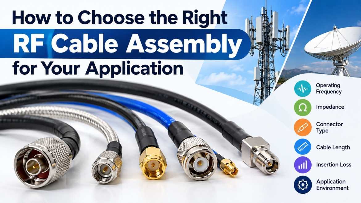
An RF Cable Assembly is an essential component in electronic communication systems that transmit radio frequency signals between devices, antennas, transmitters, receivers, and testing equipment. It consists of a coaxial cable or specialized RF cable fitted with compatible connectors to provide reliable signal transmission across a specific frequency range. Selecting the right RF Cable Assembly is important for maintaining signal integrity, minimizing transmission losses, and ensuring consistent system performance.
RF cable assemblies are widely used in telecommunications, wireless communication, aerospace, defense, satellite communication, medical electronics, radar systems, and laboratory testing. However, not every cable assembly is suitable for every application. Factors such as operating frequency, cable length, impedance, connector type, shielding, power handling, and environmental conditions influence the selection process.
Understanding these technical requirements helps engineers, system integrators, and purchasing professionals select an RF Cable Assembly that meets their performance requirements while supporting long-term reliability.
1. Understand the Operating Frequency Range
The first step in choosing the right RF Cable Assembly is determining the operating frequency of your application. Radio frequency systems operate across different frequency bands, and each cable assembly has specific electrical characteristics that determine its suitability.
For example, an RF cable assembly used in a low-frequency communication system may not deliver the same performance in a high-frequency microwave application. As frequency increases, signal attenuation and the effects of impedance mismatches become more significant.
Before selecting an assembly, identify the minimum and maximum operating frequencies of your system. Check the cable and connector specifications to ensure that the complete assembly supports the required frequency range.
For high-frequency applications, consider assemblies designed for microwave and millimeter-wave systems. These may require precision connectors, controlled manufacturing processes, and carefully selected cable materials to maintain stable electrical performance.
2. Select the Correct Impedance
Impedance matching is another important consideration when selecting an RF Cable Assembly. Most RF systems use either 50-ohm or 75-ohm characteristic impedance, depending on the application.
50-ohm RF cable assemblies are commonly used in wireless communication, radio equipment, antennas, test instruments, radar systems, and many other RF applications.
75-ohm RF cable assemblies are frequently used in television distribution, video transmission, broadcast systems, and cable infrastructure.
Choosing an assembly with the wrong impedance can create signal reflections, increase voltage standing wave ratio (VSWR), and reduce transmission efficiency. These issues can affect signal quality and the overall performance of connected equipment.
Always verify the impedance requirements of the transmitter, receiver, antenna, and other connected components before purchasing an RF Cable Assembly. Maintaining consistent impedance throughout the signal path helps minimize reflections and supports reliable transmission.
3. Choose the Appropriate Cable Type
The cable itself plays a major role in determining the electrical and mechanical performance of an RF Cable Assembly. Different cable constructions are designed for different operating conditions, frequency ranges, and installation requirements.
Common cable options include flexible coaxial cables, semi-rigid cables, semi-flexible cables, and low-loss RF cables.
Flexible Coaxial Cable
Flexible coaxial cables are suitable for installations that require easy routing, movement, or frequent equipment connections. They are commonly used in communication equipment, antennas, laboratory instruments, and general RF interconnections.
Semi-Rigid RF Cable
Semi-rigid RF cables feature a metal outer conductor that can be formed into a specific shape during installation. They provide consistent electrical characteristics and effective shielding, making them useful in microwave systems, aerospace electronics, and compact RF assemblies.
Semi-Flexible RF Cable
Semi-flexible cables offer a balance between mechanical formability and electrical performance. They can be suitable for applications requiring more routing flexibility than semi-rigid cables while maintaining controlled RF characteristics.
Low-Loss RF Cable
Low-loss cables are designed to reduce signal attenuation over the transmission path. They are useful in antenna feeder systems, telecommunications infrastructure, wireless networks, and other applications where cable length can significantly affect signal strength.
The correct choice depends on the frequency, cable routing, installation space, attenuation requirements, and expected mechanical stress.
4. Select Compatible RF Connectors
RF connectors provide the interface between the cable assembly and the connected equipment. Selecting the correct connector is essential for maintaining electrical continuity, impedance matching, and mechanical reliability.
Common RF connector types include SMA, SMB, SMC, BNC, TNC, N-Type, 2.92 mm, 3.5 mm, SMP, and SMPM connectors.
SMA connectors are widely used in compact RF equipment, wireless systems, and microwave applications. N-Type connectors are commonly used in antenna systems and communication infrastructure. BNC connectors are frequently found in laboratory instruments, video equipment, and general-purpose test systems. Precision connectors such as 2.92 mm and 3.5 mm are used in applications that require reliable performance at higher frequencies.
When selecting connectors, consider the following factors:
- Connector interface and mating compatibility
- Operating frequency range
- Characteristic impedance
- Power-handling requirements
- Connector gender and mounting configuration
- Available installation space
- Environmental sealing and durability
It is also important to distinguish between mechanically compatible connectors and electrically compatible interfaces. Similar-looking connectors may have different dimensions or performance limits. Verify the exact connector series and specifications before ordering.
5. Evaluate Insertion Loss and Signal Attenuation
Insertion loss measures the reduction in signal power caused by inserting a cable assembly into a transmission path. It is commonly expressed in decibels (dB), with lower insertion loss generally preferred when signal preservation is important.
Cable material, conductor design, dielectric properties, connector interfaces, operating frequency, and cable length all influence insertion loss.
Longer cables generally introduce greater attenuation than shorter cables of the same type. Higher operating frequencies can also increase cable losses, depending on the cable construction.
For applications such as satellite communication, wireless infrastructure, RF testing, and sensitive receiver systems, excessive attenuation can reduce the available signal level and affect system performance.
Review the manufacturer’s attenuation specifications at your intended operating frequencies and cable length. If the application has a strict loss budget, evaluate the complete assembly rather than considering the cable alone.
6. Check VSWR and Return Loss
Voltage Standing Wave Ratio (VSWR) and return loss are important parameters for evaluating how effectively an RF Cable Assembly transfers energy between connected components.
VSWR indicates the degree of impedance mismatch in a transmission line. A value closer to 1:1 indicates a better impedance match. Return loss measures the amount of signal power reflected toward the source, with higher return loss in decibels generally indicating less reflected power.
Poor connector interfaces, inconsistent impedance, damaged cables, and manufacturing defects can negatively affect these parameters.
For precision RF applications, review the specified VSWR or return loss across the complete operating frequency range. Do not assume that a cable assembly with acceptable performance at one frequency will provide the same performance at every frequency.
Where required, request test reports or production test data to verify that the assembly meets the system’s electrical specifications.
7. Consider Shielding and Electromagnetic Interference
Shielding helps protect RF signals from external electromagnetic interference (EMI) and limits unwanted radiation from the cable assembly. Effective shielding is particularly important in environments containing transmitters, switching electronics, power equipment, and multiple communication systems.
Shielding performance depends on factors such as the outer conductor, braided shielding, foil layers, connector construction, and the quality of the cable-to-connector termination.
Applications involving sensitive receivers, laboratory measurements, medical electronics, and high-density electronic installations may require careful evaluation of shielding effectiveness.
Check whether the cable assembly uses a suitable shielding construction for the application. Also consider the integrity of connector interfaces, since poorly terminated connectors can compromise the shielding performance of an otherwise suitable cable.
8. Evaluate Environmental and Mechanical Requirements
An RF Cable Assembly must withstand the physical and environmental conditions of its intended installation. Temperature, humidity, vibration, moisture, chemicals, and mechanical movement can affect cable performance and service life.
For outdoor telecommunications systems, consider weather resistance, UV exposure, moisture protection, and suitable operating temperature limits. Industrial installations may require resistance to vibration, abrasion, oils, or other environmental contaminants.
Aerospace, defense, and mobile equipment may require assemblies that tolerate repeated vibration, movement, or demanding temperature variations.
Cable flexibility is another important factor. If the assembly must bend around equipment or fit inside a compact enclosure, review the minimum bend radius specified by the manufacturer. Bending the cable beyond its permitted limit can damage the internal structure and change its electrical characteristics.
For moving installations, confirm whether the cable is rated for repeated flexing. A cable intended for static installation may not be suitable for continuous movement.
9. Determine Cable Length and Power Handling
Cable length affects attenuation, routing, installation complexity, and overall system performance. Measure the required distance between connected devices and allow sufficient length for routing, connector clearance, and servicing without introducing unnecessary excess cable.
Longer cable runs may require a larger-diameter or lower-loss cable to maintain the desired signal level. However, cable diameter and stiffness should also be considered when space and installation flexibility are limited.
Power handling is equally important when the assembly carries transmitted RF power. The permissible power depends on frequency, cable construction, connector ratings, ambient temperature, and installation conditions.
For higher-power systems, consider continuous-wave power, peak power, voltage limits, and potential heating. Power ratings can vary with frequency and environmental conditions, so confirm the manufacturer’s specifications rather than relying on a single general rating.
10. Choose a Reliable RF Cable Assembly Manufacturer
The quality of the manufacturer has a direct impact on the consistency and reliability of an RF Cable Assembly. Variations in cable materials, connector dimensions, termination processes, and assembly workmanship can affect electrical performance.
When evaluating a supplier, review its technical capabilities, manufacturing processes, quality-control procedures, and ability to meet your application requirements.
Look for detailed product specifications covering frequency range, impedance, insertion loss, VSWR or return loss, connector types, cable dimensions, temperature range, and other relevant parameters.
For customized assemblies, confirm whether the manufacturer can provide the required cable length, connector combinations, labeling, routing configuration, and electrical testing.
Depending on the application, you may also require inspection records, traceability, qualification documentation, or compliance with specified industry standards.
A reliable supplier should be able to clarify technical requirements and recommend an assembly that matches the intended operating conditions.
11. Consider Custom RF Cable Assembly Solutions
Standard RF Cable Assemblies are suitable for many applications, but some installations require custom configurations. Custom assemblies can be manufactured to meet specific cable lengths, connector combinations, routing requirements, electrical characteristics, and environmental conditions.
They are especially useful in aerospace electronics, defense systems, telecommunications equipment, wireless infrastructure, research laboratories, and specialized industrial applications.
A custom RF Cable Assembly can help simplify equipment integration and reduce the need for additional adapters. However, the design should be validated against the required electrical and mechanical specifications.
When requesting a quotation, provide the operating frequency, impedance, cable length, connector interfaces, installation environment, quantity, and performance requirements. Drawings or photographs of the intended installation can also help clarify mechanical constraints.
12. Common Mistakes to Avoid When Selecting an RF Cable Assembly
Selecting an RF Cable Assembly based only on price or physical appearance can result in compatibility issues and poor system performance.
Common mistakes include choosing the wrong impedance, overlooking connector frequency limits, using a cable with excessive attenuation, ignoring minimum bend radius, and failing to account for environmental exposure.
Another common mistake is selecting a cable based on its frequency rating without checking the performance of the complete assembly. Connector interfaces, assembly workmanship, and cable length can all influence the final result.
To avoid these problems, establish a clear specification before purchasing. Compare technical datasheets, verify connector compatibility, and request test data when performance requirements justify it.
Conclusion
Choosing the right RF Cable Assembly requires a clear understanding of electrical performance, mechanical requirements, environmental conditions, and system compatibility. Factors such as operating frequency, impedance, cable type, connector selection, insertion loss, VSWR, shielding, cable length, and power handling all contribute to reliable RF signal transmission.
For telecommunications, wireless communication, aerospace, defense, laboratory testing, and industrial electronics, selecting an assembly that meets the actual application requirements can improve signal integrity and reduce installation and maintenance problems.
Before making a purchase, review the manufacturer’s specifications, verify the compatibility of all connected components, and determine whether a standard or custom assembly is appropriate. A carefully selected RF Cable Assembly helps support dependable operation and consistent performance throughout the intended service life of the system.
FAQs About Choosing the Right RF Cable Assembly
1. What is an RF Cable Assembly?
An RF Cable Assembly is a cable fitted with compatible RF connectors that transmits radio frequency signals between electronic devices, antennas, communication equipment, and test instruments.
2. What factors should I consider when choosing an RF Cable Assembly?
Consider operating frequency, characteristic impedance, cable type, connector compatibility, insertion loss, VSWR, shielding, cable length, power handling, environmental conditions, and manufacturer quality.
3. What is the difference between a 50-ohm and a 75-ohm RF Cable Assembly?
A 50-ohm assembly is commonly used in wireless communication, RF equipment, and antenna systems, while a 75-ohm assembly is frequently used in video, broadcast, and cable distribution applications. The correct impedance depends on the connected system.
4. Which RF connector is suitable for high-frequency applications?
The appropriate connector depends on the operating frequency and performance requirements. SMA, 3.5 mm, 2.92 mm, SMP, and SMPM connectors are used in different high-frequency applications. Always verify the specified frequency range and interface compatibility.
5. Why is insertion loss important in an RF Cable Assembly?
Insertion loss indicates how much signal power is lost when a cable assembly is introduced into a transmission path. Lower insertion loss helps preserve signal strength, particularly in long cable runs and sensitive RF systems.
6. Can RF Cable Assemblies be customized?
Yes. Custom RF Cable Assemblies can be produced with specified cable lengths, connector combinations, cable types, routing configurations, and electrical performance requirements to suit particular applications.
7. How do I ensure the quality of an RF Cable Assembly?
Review the technical datasheet, verify connector and impedance compatibility, check insertion loss and VSWR specifications, evaluate the manufacturing quality, and request relevant inspection or test reports when necessary.
8. Where are RF Cable Assemblies commonly used?
RF Cable Assemblies are used in telecommunications, wireless networks, antenna systems, satellite communication, radar, aerospace, defense, medical electronics, laboratory testing, and industrial RF equipment.
9. How does cable length affect RF signal performance?
Longer cables generally introduce more attenuation. Selecting a suitable low-loss cable and evaluating the complete signal path can help maintain the required signal level.
10. Why should I choose a specialized RF Cable Assembly supplier?
A specialized supplier can help identify compatible cables and connectors, clarify electrical specifications, provide customized configurations, and support quality verification for application-specific requirements.










