
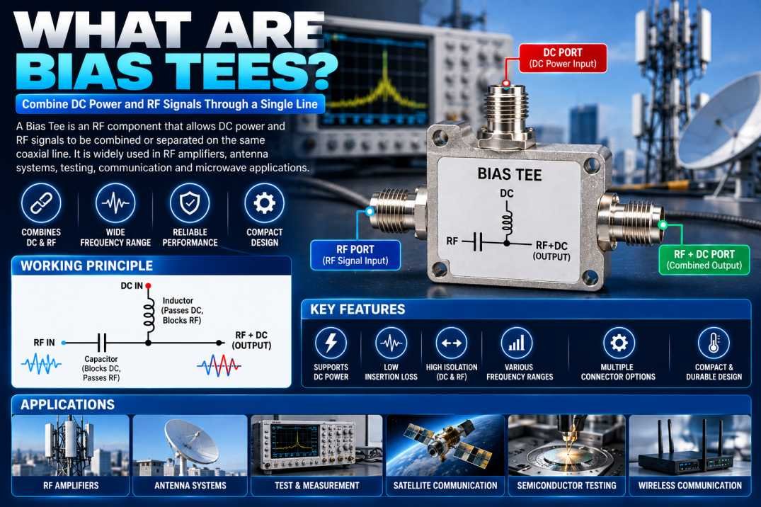
A Bias Tee is an essential RF and microwave component used to combine or separate DC power and radio frequency (RF) signals through a single coaxial transmission line. It allows DC voltage to be supplied to an active electronic device while RF signals travel through the same connection, helping simplify system design and reduce additional wiring.
Bias Tees are widely used in RF amplifiers, antenna systems, semiconductor testing, satellite communications, wireless communication equipment, microwave circuits, and laboratory test setups. Their ability to handle DC power and RF signals simultaneously makes them valuable in applications where compact design, signal integrity, and reliable power delivery are important.
Understanding the working principle, construction, specifications, and applications of Bias Tees helps engineers select the right component for their RF systems.
What Is a Bias Tee?
A Bias Tee is a three-port RF component consisting of an RF port, a DC port, and a combined RF+DC port. It uses passive circuit elements to separate the DC and RF paths while allowing both to share a common output connection.
The RF path typically uses a capacitor to block DC voltage while allowing RF signals to pass. The DC path typically uses an inductor or RF choke to supply DC while presenting high impedance to RF signals. These components help prevent unwanted interaction between the RF signal and the DC supply.
Bias Tees are available in different frequency ranges, impedance configurations, current ratings, and voltage ratings. The correct model depends on the electrical requirements of the application.
How Does a Bias Tee Work?
A Bias Tee works by using the different electrical characteristics of capacitors and inductors at DC and RF frequencies.
1. RF Signal Path
The RF input passes through a series capacitor toward the combined port. The capacitor blocks DC from entering the RF source while allowing the intended RF frequency range to pass with minimal insertion loss.
2. DC Power Path
The DC input passes through an inductor or RF choke toward the combined port. The inductor allows DC current to flow while presenting impedance to RF signals, helping prevent RF energy from entering the DC power supply.
3. Combined RF and DC Output
At the combined port, the RF signal and DC voltage share the same transmission line. The connected device receives the RF signal and the required DC bias voltage through a single connection, provided the voltage, current, frequency, and polarity are within the component’s specified limits.
Main Components of a Bias Tee
RF Capacitor
The capacitor blocks DC and passes RF signals. Its capacitance, equivalent series resistance, and parasitic characteristics affect frequency response and insertion loss.
RF Choke or Inductor
The inductor carries DC power while helping isolate RF energy from the DC supply. Its inductance, self-resonant frequency, and current rating influence the operating range.
Three RF Connections
Most Bias Tees feature three ports: RF, DC, and RF+DC. Depending on the model, these connections may use SMA, BNC, N-Type, or other coaxial interfaces.
Housing and Shielding
The housing protects internal components and supports electromagnetic shielding. A well-designed enclosure helps maintain stable RF performance and mechanical durability.
Key Features of Bias Tees
Bias Tees offer several useful features for RF and microwave systems:
- Simultaneous transmission of RF signals and DC power
- Three-port configuration for RF, DC, and combined output
- Compact integration into coaxial RF systems
- DC isolation for the RF input path
- RF isolation for the DC supply path
- Compatibility with selected RF impedance systems, commonly 50 ohms
- Availability across different frequency ranges
- Multiple connector and mounting configurations
- Options for different DC voltage and current requirements
Actual performance depends on the design and specifications of the selected Bias Tee.
Important Bias Tee Specifications
Before choosing a Bias Tee, engineers should review its main electrical parameters.
| Specification | Importance |
|---|---|
| Frequency Range | Defines the supported RF operating frequencies |
| Characteristic Impedance | Commonly 50 ohms in RF systems |
| Insertion Loss | Indicates signal power lost through the RF path |
| Return Loss or VSWR | Indicates impedance matching performance |
| Maximum DC Voltage | Defines the maximum permitted DC input |
| Maximum DC Current | Determines the supported current load |
| RF Power Handling | Specifies the allowable RF power level |
| Isolation | Indicates how effectively RF and DC paths are separated |
| Connector Type | Determines physical and electrical compatibility |
Always consult the manufacturer’s datasheet because operating limits vary by model. A Bias Tee’s maximum DC rating and RF power rating should not be assumed from its connector type or external size.
Applications of Bias Tees
RF Amplifiers and Active Devices
Bias Tees supply the DC voltage needed to operate selected RF amplifiers and other active devices while allowing RF signals to pass through the same coaxial connection.
Antenna Systems
Certain active antenna and antenna measurement setups use Bias Tees to deliver power to compatible active components without requiring a separate power cable.
Semiconductor Testing
Bias Tees are useful in semiconductor characterization and laboratory measurements where DC bias must be applied while RF signals are measured or transmitted.
Wireless Communication
RF test benches, communication modules, and selected wireless systems use Bias Tees to simplify the connection between RF equipment and DC-powered devices.
Satellite and Microwave Systems
In compatible satellite and microwave applications, Bias Tees can provide DC power to active components while maintaining an RF signal path.
Research and Development
Engineers use Bias Tees in laboratory experiments, RF circuit development, device testing, and signal characterization.
Advantages of Using Bias Tees
Simplified Wiring
A Bias Tee combines DC power and RF transmission on one coaxial connection, reducing the need for separate cables in compatible systems.
Improved System Integration
Its compact design helps integrate DC biasing into RF assemblies, laboratory equipment, and communication devices.
RF and DC Isolation
The capacitor and inductor provide frequency-dependent isolation between the RF and DC paths, helping protect connected equipment when the component is used correctly.
Flexible Testing
Bias Tees allow engineers to apply DC bias to compatible devices while monitoring or transmitting RF signals, making them valuable for testing and development.
How to Choose the Right Bias Tee
Selecting the correct Bias Tee requires careful consideration of the system’s operating conditions.
- Frequency range: Confirm that the minimum and maximum RF frequencies fall within the specified range.
- Impedance: Match the component to the system, commonly 50 ohms.
- DC voltage: Ensure the required supply voltage is below the maximum rating.
- DC current: Select a model capable of handling the expected continuous and transient current.
- RF power: Check the permitted RF power at the intended frequency and temperature.
- Insertion loss and VSWR: Choose performance suitable for the application’s signal-quality requirements.
- Connectors: Confirm compatibility with the cables and instruments being used.
- Port configuration: Verify the RF, DC, and combined-port labels before installation.
Common Mistakes to Avoid When Using Bias Tees
Using a Bias Tee outside its rated frequency range can lead to excessive signal loss or poor impedance matching. Applying too much voltage or current may damage its internal components. Connecting DC voltage to an unintended port can also damage sensitive RF equipment.
Always verify the port configuration, polarity, voltage limits, current rating, RF power handling, and grounding requirements before connecting the device. Never assume that all Bias Tees support the same frequency range or DC power levels.
Conclusion
A Bias Tee is a valuable RF component that combines DC power and RF signals on a single coaxial connection. By using a capacitor in the RF path and an inductor in the DC path, it allows compatible active devices to receive power while maintaining RF signal transmission.
Bias Tees are used in RF amplifiers, antenna systems, semiconductor testing, wireless communication, satellite equipment, microwave circuits, and research laboratories. Choosing the correct model requires evaluating frequency range, impedance, insertion loss, voltage, current, RF power handling, and connector compatibility.
For dependable performance, always select a Bias Tee that meets the requirements of the complete RF system and follow the manufacturer’s installation guidelines.
FAQs About Bias Tees
1. What is a Bias Tee used for?
A Bias Tee combines DC power and an RF signal on one coaxial line, allowing compatible electronic devices to receive power and RF signals through the same connection.
2. How does a Bias Tee work?
It typically uses a capacitor to pass RF while blocking DC and an inductor to pass DC while providing impedance to RF signals.
3. How many ports does a Bias Tee have?
A typical Bias Tee has three ports: RF, DC, and RF+DC combined.
4. What is the impedance of a Bias Tee?
Many Bias Tees are designed for 50-ohm RF systems, but the impedance should always be confirmed in the product datasheet.
5. Can a Bias Tee support high-frequency signals?
Yes, certain Bias Tees support high-frequency and microwave signals. The usable frequency range depends on the specific model.
6. Can a Bias Tee damage RF equipment?
Yes. Incorrect port connections, excessive DC voltage, excessive current, or operation beyond rated limits can damage the Bias Tee or connected equipment.
7. What is the difference between a Bias Tee and an RF splitter?
An RF splitter divides an RF signal among multiple outputs, whereas a Bias Tee combines or separates DC power and RF signals using frequency-selective components.
8. What should I check before buying a Bias Tee?
Check frequency range, impedance, insertion loss, return loss, maximum DC voltage, current capacity, RF power handling, and connector type.
9. Are Bias Tees used in antenna systems?
Yes. They can supply DC power to compatible active antennas and related RF components while allowing RF signals to travel through the same coaxial connection.
10. Does every Bias Tee support the same voltage and frequency?
No. Frequency range, voltage, current, and RF power ratings vary by model. Always verify the manufacturer’s specifications before use.










