
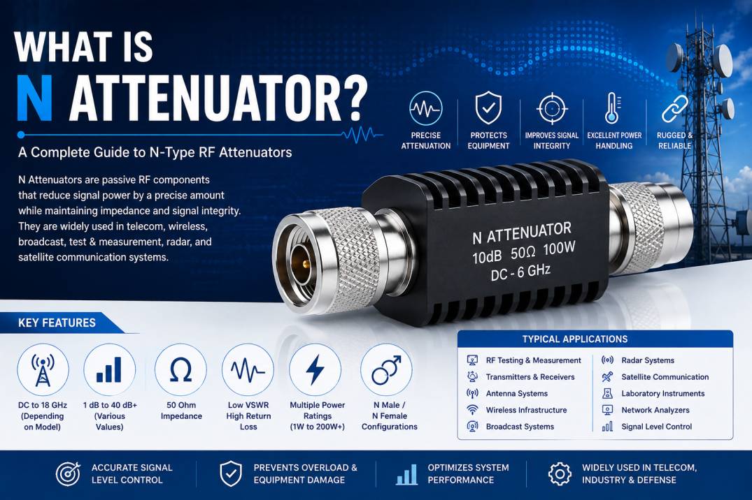
An N attenuator, also called an N-Type RF attenuator, is a passive radio frequency component used to reduce the power or amplitude of an RF signal by a predetermined amount while maintaining a controlled impedance environment. It combines an attenuation network with N-Type RF connectors, making it suitable for coaxial RF systems that require rugged mechanical performance and reliable signal-level control.
N-Type attenuators are widely used in telecommunications, wireless infrastructure, RF testing, broadcast systems, antenna systems, radar, satellite communication, industrial RF equipment, and laboratory instrumentation. Standard N-Type attenuator products are commonly designed around 50-ohm RF systems, although connector and system configurations should always be verified for the specific application. (Amphenol RF)
The primary purpose of an N attenuator is not simply to reduce signal strength. A properly designed RF attenuator can also help prevent receiver overload, protect sensitive equipment, establish required signal levels, improve impedance matching, and simplify RF system testing.
What Is an N Attenuator?
An N attenuator is an RF attenuator equipped with N-Type connectors. It is inserted into a coaxial signal path to provide a specified amount of signal attenuation.
For example, a 10 dB N-Type attenuator reduces the RF power delivered to the output by approximately 10 dB under a matched condition.
N-Type attenuators are available in different attenuation values, connector genders, frequency ranges, power ratings, and mechanical configurations.
Common attenuation values include:
- 1 dB
- 2 dB
- 3 dB
- 5 dB
- 6 dB
- 10 dB
- 15 dB
- 20 dB
- 30 dB
- 40 dB
- Higher values for specialized applications
The exact available values depend on the manufacturer’s product design. (Amphenol RF)
How Does an N-Type Attenuator Work?
An RF attenuator uses a resistive or microwave attenuation network to dissipate a controlled portion of the incoming RF energy.
When an RF signal enters the attenuator:
- The signal enters through the N-Type connector.
- The attenuation network absorbs a defined portion of RF power.
- The remaining signal continues toward the output.
- The attenuator maintains the intended impedance environment.
- The reduced RF signal exits through the second connector.
The absorbed RF energy is primarily converted into heat, which is why the power rating and thermal design are critical considerations for high-power N-Type attenuators.
Understanding Attenuation in dB
Attenuation is normally expressed in decibels, or dB.
For power attenuation:
Pout / Pin = 10^(-A/10)
Where:
- A = attenuation in dB
- Pin = input RF power
- Pout = output RF power
For example, a 3 dB attenuator reduces power to approximately half of the input power.
A 10 dB attenuator allows approximately 10% of the input power to reach the output.
A 20 dB attenuator allows approximately 1% of the input power to reach the output.
| Attenuation | Approx. Output Power |
|---|---|
| 1 dB | 79.4% |
| 3 dB | 50.1% |
| 6 dB | 25.1% |
| 10 dB | 10% |
| 20 dB | 1% |
| 30 dB | 0.1% |
| 40 dB | 0.01% |
This relationship is essential when selecting an N attenuator for transmitter, receiver, test, or measurement applications.
Why Is an N-Type Connector Used in Attenuators?
The N-Type connector is a robust coaxial RF connector commonly used in wireless infrastructure, communications, test equipment, broadcast systems, and outdoor RF installations.
Its threaded coupling provides a secure mechanical connection, making it useful in environments where vibration and mechanical stability are important.
N-Type attenuators therefore combine the signal-control function of an attenuator with the mechanical characteristics of the N-Type RF interface.
Many commercial N-Type attenuators use 50-ohm impedance and are available across frequency ranges extending into several GHz, with some specialized designs reaching considerably higher frequencies. (Amphenol RF)
Key Features of N-Type RF Attenuators
50 Ohm Impedance
Most N-Type RF attenuators used in telecommunications and RF systems are designed for a nominal 50-ohm impedance.
Maintaining impedance compatibility helps minimize reflections and preserve signal integrity.
Fixed Attenuation
Fixed N attenuators provide a predetermined attenuation value.
Common examples include:
- 3 dB
- 6 dB
- 10 dB
- 20 dB
- 30 dB
Low VSWR
A good RF attenuator should provide suitable impedance matching across its operating frequency range.
Low VSWR helps minimize reflected RF energy.
High Return Loss
Return loss indicates how much of the signal is reflected toward the source.
Higher return loss generally indicates better matching.
Rugged Construction
N-Type attenuators can use metal housings designed for mechanical durability and thermal management.
Passive Operation
An N-Type attenuator does not require an external power supply to perform its basic attenuation function.
Multiple Power Ratings
N-Type attenuators are available for low-power laboratory systems as well as high-power RF applications. Commercial examples range from a few watts to hundreds of watts depending on frequency, attenuation, cooling, and construction. (RF Microwave)
Types of N-Type Attenuators
N attenuators can be classified according to attenuation behavior, connector configuration, power handling, and application.
1. Fixed N-Type Attenuator
A fixed N-Type attenuator provides one predetermined attenuation value.
For example:
N-Type 10 dB Fixed Attenuator
The attenuation remains nominally 10 dB throughout the specified operating frequency range, subject to the manufacturer’s accuracy and flatness specifications.
Applications
- RF testing
- Wireless systems
- Signal-level adjustment
- Receiver protection
- Transmitter testing
- Laboratory measurement
Fixed attenuators are one of the most common N-Type attenuator configurations. (Amphenol RF)
2. N-Type Bidirectional Attenuator
A bidirectional N attenuator can be inserted into an RF path in either direction while providing essentially the same nominal attenuation.
This makes it convenient for systems where the direction of signal flow can change.
Applications
- RF test benches
- Cable testing
- Antenna testing
- Wireless communication
- Laboratory instrumentation
- RF system integration
3. N-Type Unidirectional Attenuator
A unidirectional attenuator is designed around a defined input and output configuration.
Such components can be selected for specialized applications where the RF path and power flow have defined requirements.
The manufacturer’s specifications should always be checked before using a particular attenuator in a directional application. (SRFSTELEINFRA)
4. High-Power N-Type Attenuator
High-power N attenuators are designed to dissipate substantial RF energy.
When RF power is attenuated, the absorbed energy becomes heat. Therefore, high-power attenuators may incorporate larger housings, heat sinks, fins, or other thermal-management structures.
Commercial N-Type high-power examples are available at ratings such as 30 W, 100 W, and 200 W, depending on frequency and model. (RF Microwave)
5. Low-Power N-Type Attenuator
Low-power N attenuators are typically used in:
- RF laboratories
- Communication equipment
- Receiver testing
- Signal generators
- Spectrum analyzers
- Network analyzers
- Prototype RF systems
Their compact size and lower power requirements make them suitable for signal conditioning and measurement applications.
6. Precision N-Type Attenuator
Precision N-Type attenuators are manufactured to provide accurate attenuation, low VSWR, and stable electrical characteristics.
They are particularly valuable for:
- RF calibration
- Test and measurement
- Instrumentation
- Production testing
- System verification
N-Type Attenuator Connector Configurations
N-Type attenuators are available with different connector gender configurations.
Common configurations include:
- N Male to N Female
- N Female to N Female
- N Male to N Male
The most suitable configuration depends on the equipment and coaxial cable assembly being connected.
An N Male-to-N Female inline attenuator can often be inserted directly into an existing coaxial signal path without requiring an additional adapter.
N-Type Attenuator Technical Specifications
Important specifications include:
| Parameter | Description |
|---|---|
| Connector | N-Type |
| Impedance | Typically 50 Ohm |
| Attenuation | Application dependent |
| Frequency Range | Model dependent |
| Power Rating | Application dependent |
| VSWR | Model dependent |
| Return Loss | Model dependent |
| Attenuation Accuracy | Model dependent |
| Attenuation Flatness | Model dependent |
| Connector Gender | Male/Female combinations |
| Housing | RF-grade metal |
| Operating Temperature | Model dependent |
Actual specifications vary significantly between models. A manufacturer’s datasheet should always be used when selecting a component for a specific RF system. (Amphenol RF)
N Attenuator Frequency Range
Frequency range is one of the most important specifications when selecting an RF attenuator.
An attenuator must provide acceptable electrical performance throughout the required operating band.
For example, commercial N-Type attenuators are available for applications extending to:
- 3 GHz
- 6 GHz
- 12.4 GHz
- 18 GHz
- Other specialized frequency ranges
However, frequency capability is product-specific. The N-Type connector itself should not be treated as a guarantee that every N attenuator will operate at the same maximum frequency. (Fairview Microwave)
N-Type Attenuator Power Rating
Power handling is particularly important in RF transmitters, amplifiers, antenna systems, and RF test equipment.
If the input power is too high for the attenuator, excessive heat can cause:
- Component failure
- Resistance changes
- Connector damage
- Performance degradation
- Permanent electrical damage
For this reason, always check the specified continuous-wave power rating and any applicable peak-power rating.
For high-power applications, thermal derating may also be required.
Continuous Power vs Peak Power
RF attenuators may specify both continuous and peak power ratings.
Continuous Power
Continuous power refers to the RF power the attenuator can handle continuously under specified conditions.
Peak Power
Peak power refers to short-duration RF power that the attenuator can tolerate under defined pulse width and duty-cycle conditions.
A peak-power specification must not be interpreted as a continuous operating rating.
VSWR in N-Type Attenuators
VSWR, or Voltage Standing Wave Ratio, measures the degree of impedance mismatch in an RF system.
A lower VSWR generally indicates better matching.
An N attenuator with low VSWR can reduce unwanted reflections and help maintain predictable RF performance.
For example, commercial N-Type attenuator specifications may list VSWR values such as 1.15:1 or 1.25:1 depending on frequency and model. (RF Microwave)
Return Loss of N Attenuators
Return loss measures the amount of RF power reflected back toward the source due to impedance mismatch.
A higher return loss generally indicates a better impedance match.
Good return loss is important in:
- RF transmitters
- Receivers
- Antenna systems
- Test equipment
- Signal generators
- RF amplifiers
Attenuation Accuracy
The nominal attenuation value does not necessarily represent the exact attenuation at every frequency.
For example, a 10 dB attenuator may have an attenuation tolerance or frequency-dependent variation.
Precision applications therefore require attention to:
- Attenuation accuracy
- Attenuation flatness
- Frequency range
- VSWR
- Temperature stability
Attenuation Flatness
Attenuation flatness describes how consistently the attenuation remains close to its nominal value across the specified frequency range.
For broadband RF applications, flat attenuation is important because significant variation can affect signal-level accuracy.
Insertion Loss and Attenuation
Insertion loss and attenuation are related but should not be treated as identical specifications.
An ideal attenuator produces its intended attenuation while introducing predictable behavior within the RF system.
The manufacturer’s datasheet should be consulted for insertion loss, attenuation accuracy, and other frequency-dependent specifications.
Applications of N-Type Attenuators
N-Type attenuators are used across many RF and microwave applications.
Telecommunications
N attenuators can be used for signal-level management in wireless infrastructure and RF communication equipment.
RF Testing
Test laboratories use attenuators to establish controlled signal levels between RF instruments and devices under test.
Antenna Testing
An attenuator can be inserted into an antenna measurement path to adjust signal levels or protect sensitive equipment.
Transmitter Systems
High-power N attenuators can be used for controlled loading, power-level adjustment, and transmitter testing when the attenuator is appropriately rated.
Receiver Protection
An attenuator can reduce a high-level input signal before it reaches a sensitive receiver stage.
RF Amplifier Testing
Attenuators can help establish suitable input and output levels during amplifier characterization.
Broadcast Systems
N-Type RF components are frequently used in radio-frequency infrastructure, and compatible attenuators can provide controlled signal reduction.
Radar Systems
RF attenuators can be used for testing, calibration, signal conditioning, and controlled RF power levels.
Satellite Communication
Depending on frequency and connector requirements, precision RF attenuators can be used in satellite communication test and signal-chain applications.
Laboratory Instrumentation
RF signal generators, spectrum analyzers, power meters, and network analyzers can use attenuators for signal-level control and equipment protection.
N-Type Attenuators in 5G and Wireless Infrastructure
Modern wireless infrastructure requires accurate RF signal management across multiple frequency ranges.
N-Type attenuators can be useful in:
- Base-station testing
- RF front-end testing
- Antenna systems
- Distributed antenna systems
- Wireless links
- RF cable assemblies
- Field measurement equipment
The exact attenuator frequency range and power handling must match the wireless system.
N Attenuators for RF Cable Assemblies
An N-Type attenuator can be integrated into coaxial RF systems using N-Type cable assemblies.
For example:
RF Equipment → N-Type Cable → N Attenuator → N-Type Cable → Antenna/System
This configuration allows engineers to reduce the signal level without redesigning the complete cable system.
The cable loss, connector loss, attenuator loss, and system impedance should all be considered when calculating the overall RF link budget.
Advantages of N-Type RF Attenuators
Robust Mechanical Design
N-Type connectors are suitable for applications requiring secure threaded connections.
Controlled Signal Reduction
Fixed attenuation allows engineers to reduce RF power by a known amount.
Wide Application Range
N attenuators can be used in telecom, test equipment, wireless infrastructure, broadcast, radar, and industrial RF systems.
Equipment Protection
They can help prevent excessive signal levels from reaching sensitive RF components.
Improved Test Flexibility
Different attenuation values allow engineers to create controlled RF test conditions.
Passive Operation
No external DC power is required for basic attenuation.
High-Power Options
Specialized N-Type attenuators are available for high-power RF systems. (RF Microwave)
Limitations of N-Type Attenuators
Although N attenuators are highly useful, they also have limitations.
Signal Power Is Lost
The primary function of an attenuator is to reduce RF power, so it cannot increase signal strength.
Heat Generation
The attenuated RF energy is converted into heat.
Frequency Dependence
Attenuation, VSWR, and other electrical characteristics can change with frequency.
Physical Size
N-Type attenuators are generally larger than miniature RF attenuator formats such as SMA, 2.92 mm, 2.4 mm, or 1.85 mm.
Power Derating
High-power operation may require derating depending on ambient temperature and cooling conditions.
N Attenuator vs N-Type Termination
An N attenuator and an N-Type termination perform different functions.
| Feature | N Attenuator | N-Type Termination |
|---|---|---|
| Main Function | Reduce RF signal | Absorb RF signal |
| Output Port | Yes | Usually terminated |
| Attenuation | Defined dB value | Not primary function |
| Typical Use | Signal-level control | Port termination |
| RF Path | Pass-through | End of RF path |
| Common Values | 1–40+ dB | 50 Ohm termination |
| Power Handling | Model dependent | Model dependent |
An attenuator is inserted into the RF path, whereas a termination is generally used to terminate an unused or test port with the appropriate impedance.
N Attenuator vs RF Amplifier
An attenuator reduces RF signal power, while an amplifier increases RF signal power.
| Parameter | N Attenuator | RF Amplifier |
|---|---|---|
| Signal Level | Decreases | Increases |
| External Power | Not required | Required |
| Main Function | Signal control | Signal amplification |
| Heat | Dissipates RF energy | Generates operating heat |
| Gain | Negative | Positive |
| Typical Use | Level adjustment | Signal amplification |
How to Select the Right N-Type Attenuator
Selecting an N attenuator requires more than choosing the desired dB value.
1. Determine the Required Attenuation
Calculate how much signal reduction is necessary.
2. Check Frequency
The attenuator must cover the complete operating frequency range.
3. Check Input Power
Determine the maximum continuous and peak RF power.
4. Check Impedance
Ensure the attenuator is compatible with the system impedance, typically 50 ohms for standard N-Type RF systems.
5. Check VSWR
Select an attenuator with suitable VSWR for the application.
6. Check Attenuation Accuracy
Precision RF measurement systems may require tight attenuation tolerance.
7. Select Connector Gender
Choose the appropriate N Male, N Female, or other required configuration.
8. Consider Environmental Conditions
Outdoor systems may require suitable temperature performance, corrosion resistance, sealing, or weather-resistant construction.
9. Consider Thermal Management
High-power applications may require heat sinks or other thermal-management features.
10. Check Mechanical Requirements
Consider dimensions, mounting, connector torque, mating cycles, and available installation space.
Common Mistakes When Selecting an N Attenuator
Selecting Based Only on dB Value
A 10 dB attenuator is not automatically suitable simply because 10 dB is the required attenuation. Frequency, power, VSWR, and accuracy must also be considered.
Ignoring Frequency
Using an attenuator beyond its specified frequency range can result in unpredictable RF performance.
Exceeding the Power Rating
Operating above the specified power rating can cause overheating and permanent damage.
Ignoring Cable Loss
The attenuator is only one part of the RF link budget. Cable and connector losses must also be considered.
Using the Wrong Connector Configuration
An N Male-to-N Male component may not be suitable when the equipment requires an N Male-to-N Female connection.
Ignoring Environmental Requirements
Outdoor telecom applications may require mechanical and environmental protection that a basic laboratory attenuator does not provide.
Maintenance of N-Type Attenuators
Proper maintenance can help preserve RF performance.
Recommended practices include:
- Keep connectors clean.
- Avoid excessive mechanical force.
- Use the manufacturer’s recommended torque.
- Protect connectors from moisture and contamination.
- Inspect connector surfaces for damage.
- Avoid exceeding rated RF power.
- Follow specified temperature limits.
- Store components in suitable environmental conditions.
Testing N-Type Attenuators
N attenuators can be tested using RF test equipment such as:
- Vector Network Analyzers
- Spectrum Analyzers
- RF Signal Generators
- Power Meters
- Network Test Systems
Important parameters to evaluate include:
- Attenuation
- Return loss
- VSWR
- Insertion loss
- Frequency response
- Power handling
- Temperature stability
For precision measurement applications, appropriate calibration and test fixtures are essential.
N-Type Attenuator Manufacturing Considerations
High-quality N attenuators require controlled mechanical and electrical manufacturing processes.
Important manufacturing considerations include:
- Precision RF resistor networks
- Accurate impedance control
- High-quality dielectric materials
- Reliable center contacts
- Precision-machined connectors
- Suitable plating
- Thermal management
- Controlled assembly
- RF performance testing
Manufacturing quality directly affects attenuation accuracy, VSWR, return loss, power handling, and long-term reliability.
Why Choose a High-Quality N Attenuator?
A high-quality N-Type attenuator can provide:
- Stable attenuation
- Reliable impedance matching
- Low VSWR
- Consistent RF performance
- Robust mechanical construction
- Better thermal performance
- Reliable connector interfaces
- Longer service life
For critical RF systems, product specifications should be evaluated against the complete system requirements rather than selecting solely on price.
Conclusion
An N attenuator is a passive RF component designed to provide controlled signal reduction in coaxial RF systems using N-Type connectors. It is widely used for signal-level control, equipment protection, RF testing, antenna measurements, transmitter testing, telecommunications, broadcast, radar, satellite communication, and wireless infrastructure.
The most important specifications when selecting an N-Type attenuator include attenuation value, frequency range, impedance, power rating, VSWR, return loss, attenuation accuracy, connector gender, and environmental performance.
For low-power laboratory systems, compact fixed N attenuators may be sufficient. For transmitter and RF infrastructure applications, high-power N-Type attenuators with appropriate thermal management may be required.
A correctly selected N attenuator helps create a controlled, predictable, and reliable RF signal path.
Frequently Asked Questions About N Attenuators
1. What is an N attenuator?
An N attenuator is a passive RF component that reduces signal power by a specified amount and uses N-Type RF connectors for integration into coaxial RF systems.
2. What is the impedance of an N-Type attenuator?
Most N-Type RF attenuators used in telecommunications and RF applications are designed for 50-ohm systems. Always verify the product datasheet for the exact configuration.
3. What are common N attenuator values?
Common attenuation values include 1 dB, 3 dB, 6 dB, 10 dB, 20 dB, 30 dB, and 40 dB, with other values available for specialized applications. (Amphenol RF)
4. What does a 10 dB N attenuator do?
A 10 dB attenuator reduces the RF power to approximately 10% of the input power under matched conditions.
5. Are N-Type attenuators bidirectional?
Many fixed N-Type attenuators are designed for bidirectional operation, but this should be confirmed from the manufacturer’s specifications before installation.
6. Can an N attenuator handle high RF power?
Yes. High-power N-Type attenuators are available, but their power ratings vary significantly. Some commercial models are rated at tens or hundreds of watts depending on frequency and thermal design. (RF Microwave)
7. What is the difference between an N attenuator and an N termination?
An N attenuator reduces the signal while allowing it to continue through the RF path. An N termination is normally used to terminate an RF port with the required impedance.
8. Does an N attenuator need a power supply?
No. A standard passive N-Type attenuator does not require an external power supply.
9. Can an N attenuator protect an RF receiver?
Yes. An appropriately rated attenuator can reduce the signal level entering a sensitive receiver and help prevent overload, provided the attenuation and power ratings are correctly selected.
10. What is VSWR in an N attenuator?
VSWR indicates the degree of impedance mismatch between the attenuator and the connected RF system. Lower VSWR generally indicates better matching.
11. What frequency range can an N attenuator support?
The frequency range depends on the particular attenuator. Commercial N-Type products are available from low frequencies through several GHz, with specialized designs extending to higher frequencies. (Amphenol RF)
12. Where are N-Type attenuators used?
They are used in telecommunications, wireless infrastructure, RF laboratories, antenna systems, broadcast equipment, radar, satellite communication, RF testing, transmitters, receivers, and industrial RF systems.
13. How do I choose an N-Type attenuator?
Consider the required attenuation, frequency range, RF power, impedance, VSWR, return loss, connector gender, environmental conditions, and mechanical requirements.
14. Can N attenuators be used outdoors?
Yes, provided the selected model has suitable environmental, temperature, mechanical, and weather-resistance specifications for the intended outdoor installation.
15. Why is power rating important in an N attenuator?
An attenuator converts part of the RF energy into heat. If the input power exceeds the component’s rated capacity, excessive heating can damage the attenuation network and connector assembly.
16. What is a high-power N-Type attenuator?
A high-power N-Type attenuator is designed to dissipate significantly more RF energy than standard low-power models and may incorporate heat sinks or other thermal-management structures.
17. Can N attenuators be used for 5G applications?
Yes. N-Type attenuators can be used in suitable 5G RF infrastructure and test applications when their frequency range, power handling, impedance, and other specifications match the system requirements.
18. Are N attenuators available in male-to-female configurations?
Yes. N Male-to-N Female is a common inline configuration, although N Female-to-N Female and other configurations are also available depending on the application.
19. Does a higher dB value mean better attenuation?
A higher dB value means greater signal reduction, not necessarily better performance. The correct attenuation value depends on the RF system’s signal-level requirements.
20. Why are N-Type attenuators important in RF systems?
N-Type attenuators provide controlled RF signal reduction while maintaining a standardized coaxial interface, making them valuable for signal management, equipment protection, testing, calibration, and RF system integration.
:::










