
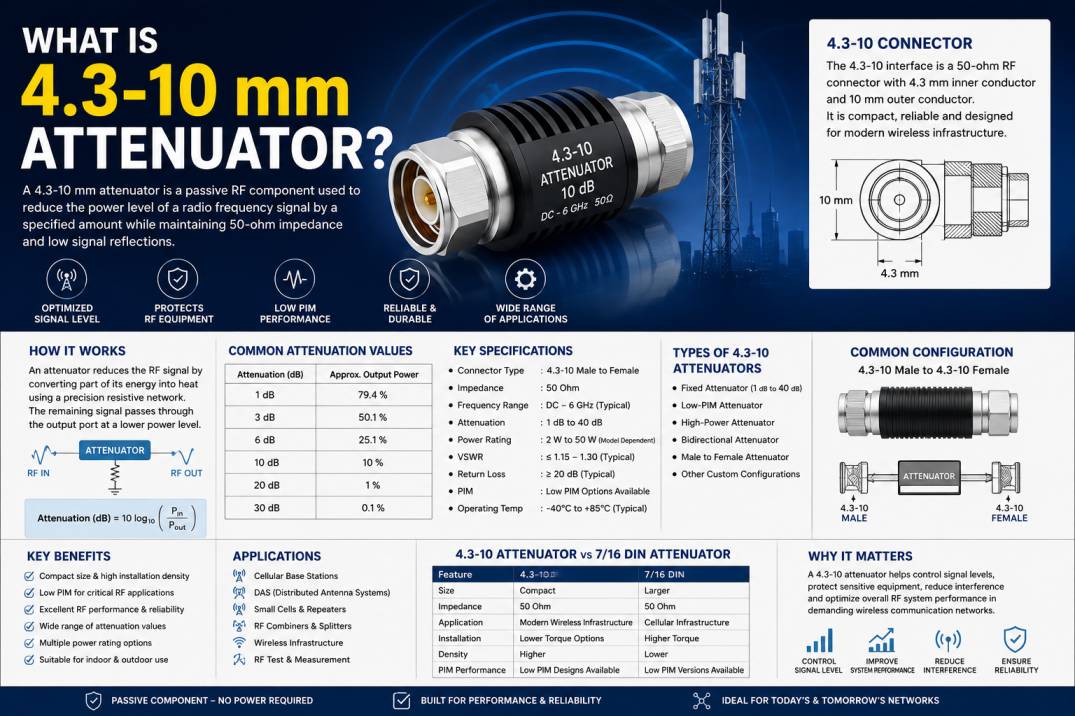
A 4.3-10 mm attenuator, more commonly written as a 4.3-10 RF attenuator or 4.3/10 attenuator, is a passive RF component used to reduce the power level of a radio frequency signal by a specified amount while maintaining a controlled impedance and minimizing unwanted signal reflections.
The 4.3-10 interface is a 50-ohm RF connector system developed for modern wireless and telecommunications infrastructure. The connector has a smaller footprint than traditional 7/16 DIN interfaces while providing features suited to cellular and high-performance RF installations. (Wikipedia)
A 4.3-10 attenuator combines this RF connector interface with an attenuation network that reduces signal amplitude by a defined value, such as 1 dB, 3 dB, 6 dB, 10 dB, 20 dB, or other specified levels.
These attenuators are widely used in cellular networks, Distributed Antenna Systems (DAS), base stations, RF test equipment, wireless infrastructure, repeaters, transmitters, receivers, and signal distribution systems.
What Does 4.3-10 Mean?
The term 4.3-10 refers to the mechanical dimensions of the RF connector interface.
The connector uses an approximately 4.3 mm inner conductor diameter and a 10 mm outer-conductor dimension, with the interface standardized under IEC 61169-54. It is a 50-ohm RF connector designed for demanding wireless communication applications. (Wikipedia)
The 4.3-10 connector was developed as a more compact alternative to larger connector systems such as 7/16 DIN, particularly for modern mobile communication infrastructure.
Key Characteristics of the 4.3-10 Interface
- 50-ohm impedance
- Compact RF interface
- Suitable for cellular infrastructure
- Low-PIM designs are widely available
- Multiple coupling mechanisms
- Suitable for high-density installations
- Designed for reliable RF performance
- Commonly used up to 6 GHz, with some connector products extending to 12 GHz (Amphenol RF)
What Is an RF Attenuator?
An RF attenuator is a passive two-port component that intentionally reduces the power or voltage level of an RF signal.
For example, a 10 dB attenuator reduces the signal power by a factor of 10.
The primary purposes of an RF attenuator include:
- Reducing excessive signal power
- Preventing receiver overload
- Protecting sensitive RF equipment
- Controlling signal levels
- Improving impedance matching
- Reducing unwanted reflections
- Balancing RF distribution systems
- Supporting RF testing and measurement
An attenuator does not normally amplify the signal. It introduces a controlled amount of loss.
What Is a 4.3-10 RF Attenuator?
A 4.3-10 RF attenuator is therefore an attenuator equipped with 4.3-10 RF interfaces.
A common configuration is:
4.3-10 Male → 4.3-10 Female
This allows the attenuator to be installed directly between compatible RF equipment, coaxial cables, antennas, filters, combiners, or other passive RF components.
Commercial 4.3-10 attenuators are available in various attenuation values and power ratings. For example, current products include 1 dB, 3 dB, 10 dB and 20 dB versions, with specifications varying by manufacturer and model. (element14)
How Does a 4.3-10 Attenuator Work?
A 4.3-10 attenuator works by incorporating a precisely designed resistive or thin-film attenuation network into a controlled RF transmission path.
When an RF signal enters the attenuator, part of its energy is dissipated as heat. The remaining signal continues through the output port at a lower power level.
For example, consider a 10 dB attenuator.
If the input power is 10 W, the ideal output power is:
Output Power = 10 W × 10^(-10/10)
Therefore:
Output Power = 1 W
The remaining RF energy is dissipated within the attenuator.
Why Is Attenuation Measured in Decibels?
RF attenuation is normally specified in decibels (dB).
The power attenuation relationship is:
Attenuation (dB) = 10 log10(Pin/Pout)
Where:
- Pin = Input power
- Pout = Output power
Common attenuation values include:
| Attenuation | Approximate Output Power |
|---|---|
| 1 dB | 79.4% |
| 3 dB | 50.1% |
| 6 dB | 25.1% |
| 10 dB | 10% |
| 20 dB | 1% |
| 30 dB | 0.1% |
For example, if a 100 W RF signal passes through a theoretical 20 dB attenuator, approximately 1 W remains at the output.
Main Types of 4.3-10 Attenuators
4.3-10 attenuators can be categorized according to attenuation behavior, configuration, power rating, and application.
1. Fixed 4.3-10 Attenuator
A fixed attenuator provides a predetermined attenuation value.
Typical values include:
- 1 dB
- 2 dB
- 3 dB
- 5 dB
- 6 dB
- 10 dB
- 15 dB
- 20 dB
- 30 dB
- 40 dB
The exact available values depend on the manufacturer.
Fixed attenuators are commonly used when the required signal reduction is known in advance.
2. Low-PIM 4.3-10 Attenuator
Low-PIM attenuators are designed for cellular and wireless infrastructure where passive intermodulation performance is important.
PIM, or Passive Intermodulation, occurs when nonlinearities in passive RF components generate unwanted mixing products.
Low-PIM attenuators are particularly important in:
- Cellular base stations
- DAS networks
- Small cells
- Antenna systems
- RF combiners
- Repeater systems
- Public safety communication networks
4.3-10 components are widely used in modern wireless infrastructure partly because the interface was designed with low-PIM requirements in mind. (Amphenol RF)
3. High-Power 4.3-10 Attenuator
High-power attenuators are designed to dissipate larger amounts of RF energy.
The power rating depends on:
- Attenuation value
- Frequency
- Internal resistor technology
- Thermal design
- Housing construction
- Ambient temperature
- Duty cycle
- Cooling conditions
Commercial examples range from low-power versions to products rated at tens of watts, demonstrating why the exact datasheet must be checked for every model. (element14)
4. Bidirectional 4.3-10 Attenuator
Many passive fixed attenuators can operate in either direction electrically, meaning the RF signal can enter from either port.
This can be useful in RF distribution and test systems where signal direction may change.
However, the manufacturer should specify whether a particular model is bidirectional.
5. Male-to-Female 4.3-10 Attenuator
One of the most common configurations is:
4.3-10 Male to 4.3-10 Female
This inline format allows the attenuator to connect directly between a compatible male and female RF interface.
Commercial 4.3-10 male-to-female attenuators are available with different attenuation and power specifications. (ANDREW)
Important Specifications of a 4.3-10 Attenuator
When selecting a 4.3-10 RF attenuator, several technical specifications must be considered.
Frequency Range
Frequency range indicates the frequencies over which the attenuator meets its specified electrical performance.
Many commercially available 4.3-10 attenuators are specified up to 6 GHz, while specific products may have different operating ranges. (element14)
Attenuation Value
The attenuation value indicates how much signal power is reduced.
Typical values include:
- 1 dB
- 3 dB
- 6 dB
- 10 dB
- 20 dB
- 30 dB
Impedance
Most 4.3-10 wireless infrastructure attenuators are designed for:
50 Ohms
Maintaining 50-ohm impedance helps achieve proper RF system matching.
Power Rating
Power rating indicates the maximum RF power the attenuator can handle under specified conditions.
Examples from current products show ratings such as 2 W, 10 W, 15 W, and 50 W, illustrating that power capability is highly model-specific. (element14)
Never select an attenuator solely by its attenuation value. Its power rating must also be suitable for the application.
VSWR
VSWR, or Voltage Standing Wave Ratio, indicates how well the attenuator is matched to the RF system.
A lower VSWR generally indicates better impedance matching and lower reflections.
For example, some commercial 4.3-10 attenuators specify maximum VSWR values around 1.15:1 to 1.3:1, depending on the model. (Fairview Microwave)
Return Loss
Return loss measures the amount of RF power reflected toward the source.
Higher return loss generally indicates better impedance matching.
Some 4.3-10 attenuator products specify return-loss performance above 20 dB across their operating range. (ANDREW)
PIM Performance
For cellular applications, PIM is a critical specification.
A low-PIM attenuator minimizes unwanted passive intermodulation products that could interfere with sensitive receivers.
Operating Temperature
The operating temperature specification defines the environmental temperature range within which the attenuator is designed to maintain its specified performance.
Current commercial products show different temperature ranges, such as -40°C to +85°C or -55°C to +125°C, depending on design. (element14)
Typical 4.3-10 Attenuator Specifications
The following table represents common specification categories rather than a single universal product specification.
| Parameter | Typical Requirement |
|---|---|
| Connector | 4.3-10 |
| Impedance | 50 Ohms |
| Attenuation | 1–40 dB, depending on model |
| Frequency | DC–6 GHz commonly available |
| VSWR | Model dependent |
| Power | Model dependent |
| PIM | Low-PIM options available |
| Configuration | Male-to-Female commonly available |
| Design | Fixed passive |
| Application | Telecom and RF infrastructure |
Actual specifications must always be verified against the individual manufacturer’s datasheet. (element14)
4.3-10 Attenuator vs 7/16 DIN Attenuator
The 4.3-10 connector was developed partly as a more compact alternative to 7/16 DIN in mobile communication applications.
| Feature | 4.3-10 | 7/16 DIN |
|---|---|---|
| Size | Compact | Larger |
| Impedance | 50 Ohm | 50 Ohm |
| Application | Modern wireless infrastructure | Cellular infrastructure |
| Installation | Lower torque options | Higher torque traditionally |
| Density | Higher connector density | Lower than 4.3-10 |
| PIM | Designed for low-PIM applications | Low-PIM versions available |
| Coupling | Multiple options | Threaded |
The 4.3-10 interface was designed to reduce footprint and required mating torque while supporting reliable RF performance in modern mobile networks. (Wikipedia)
Advantages of 4.3-10 RF Attenuators
Compact Design
The 4.3-10 interface provides a smaller footprint than traditional 7/16 DIN systems.
Low-PIM Availability
Low-PIM 4.3-10 attenuators are suitable for demanding cellular and DAS installations.
Reliable RF Performance
Precision RF construction helps maintain controlled impedance, low reflection, and predictable attenuation.
Multiple Coupling Options
The 4.3-10 connector family supports different coupling mechanisms, including screw-on, hand-tightened, and quick-release configurations. (Wikipedia)
High Installation Density
The smaller interface allows more RF connections within constrained equipment and panel spaces.
Flexible Attenuation Options
Different attenuation values allow engineers to precisely control RF signal levels.
Applications of 4.3-10 Attenuators
Cellular Base Stations
4.3-10 attenuators are used in cellular infrastructure to manage RF signal levels between radios, filters, combiners, antennas, and other passive components.
Distributed Antenna Systems
DAS networks use RF attenuators to balance signal levels across different branches of a distribution network.
Small Cell Networks
Small cells require compact RF components capable of reliable performance in space-constrained installations.
RF Repeaters
Attenuators can be used to control signal levels in repeater systems and prevent excessive input levels.
RF Combiners and Splitters
Attenuators can help balance individual signal paths when multiple RF signals are combined or distributed.
Wireless Infrastructure
4.3-10 attenuators are used in antennas, remote radio systems, filters, amplifiers, and other telecom infrastructure.
RF Testing and Measurement
Attenuators are useful in laboratory and production environments for controlling signal levels entering:
- Spectrum analyzers
- Signal generators
- Power meters
- Receivers
- Amplifiers
- RF test systems
How to Select a 4.3-10 Attenuator
Choosing the right attenuator requires evaluating the complete RF system.
1. Determine the Required Attenuation
First calculate how much signal reduction is required.
For example, if the input signal is too high by approximately 10 dB, a 10 dB attenuator may be appropriate.
2. Check the Frequency Range
Ensure the attenuator supports the complete operating frequency range of the system.
3. Check the Power Level
The attenuator must safely dissipate the expected RF power.
A 10 W RF signal should not be connected to a component rated for only 2 W.
4. Check the Connector Configuration
Verify whether the system requires:
- 4.3-10 Male
- 4.3-10 Female
- Male-to-Female
- Female-to-Female
- Other configurations
5. Consider PIM
For cellular and DAS systems, select a low-PIM model where required.
6. Evaluate VSWR and Return Loss
Good matching helps minimize reflections and maintain system performance.
7. Check Environmental Requirements
For outdoor installations, consider:
- Temperature
- Moisture
- Dust
- UV exposure
- Corrosion
- Weatherproofing
- IP rating
4.3-10 Attenuator for DAS Networks
Distributed Antenna Systems are an important application for 4.3-10 attenuators.
A DAS distributes RF signals throughout a building, stadium, airport, tunnel, campus, or other large facility.
Because different branches may have different cable lengths and losses, signal levels need to be carefully balanced.
Attenuators can be installed within specific branches to reduce excessive RF power and help achieve the desired signal distribution.
Low-PIM performance is particularly important because unwanted passive intermodulation can degrade cellular network performance.
4.3-10 Attenuator for 5G Infrastructure
5G infrastructure uses a wide range of RF passive components, including:
- Attenuators
- Filters
- Couplers
- Splitters
- Combiners
- Adapters
- Terminations
- Cable assemblies
4.3-10 components are particularly relevant in RF infrastructure where compact size, low PIM, and reliable mechanical connectivity are required.
However, the suitability of a specific 4.3-10 attenuator for a particular 5G frequency band must always be confirmed from its electrical specifications.
4.3-10 Attenuator vs RF Termination
Although both are passive RF components, they perform different functions.
| Feature | 4.3-10 Attenuator | 4.3-10 Termination |
|---|---|---|
| Main Function | Reduces signal level | Absorbs signal at unused port |
| Ports | Two | One |
| Signal Passes Through | Yes | No |
| Attenuation | Defined value | Usually specified as matched load |
| Application | Signal control | Port termination |
| Typical Use | RF level management | Preventing reflections |
An attenuator is installed in the signal path, while a termination is generally connected to an unused RF port.
4.3-10 Attenuator vs 4.3-10 Adapter
A 4.3-10 adapter primarily provides a mechanical and electrical transition between RF interfaces.
An attenuator performs an additional function: it deliberately reduces RF power.
Therefore:
Adapter = Interface conversion
Attenuator = Controlled signal reduction
Why Low-PIM Matters in 4.3-10 Attenuators
Passive components can generate intermodulation products when exposed to multiple RF signals.
In cellular systems, these unwanted products may fall within sensitive receiver bands.
Low-PIM design can therefore be important in:
- LTE networks
- 5G networks
- DAS
- Base stations
- Public safety systems
- RF distribution networks
Connector quality, contact design, surface finish, mechanical stability, and manufacturing precision can all influence PIM performance.
Thermal Considerations
RF attenuation converts part of the signal energy into heat.
For a fixed attenuator, the dissipated power can be approximated by:
Pdissipated = Pin − Pout
For example, with 10 W input power and a 3 dB attenuation:
Pout ≈ 5.01 W
Approximately:
Pdissipated ≈ 4.99 W
This is why high-power attenuators require appropriate thermal design.
Installation Considerations
Proper installation is essential for reliable RF performance.
Keep Connectors Clean
Dust, moisture, and contamination can affect RF contact performance.
Use Correct Mating Procedures
Follow the connector manufacturer’s recommended mating and tightening procedure.
Avoid Excessive Mechanical Stress
Do not use the attenuator as a mechanical support for heavy cables.
Verify Power Before Installation
Ensure that the RF power level does not exceed the component’s specified rating.
Consider Outdoor Protection
Outdoor applications may require weatherproof components and suitable sealing practices.
Common Mistakes When Using 4.3-10 Attenuators
Using an Incorrect Power Rating
One of the most serious mistakes is selecting an attenuator based only on attenuation value without checking power handling.
Ignoring Frequency
A component rated for 6 GHz should not automatically be used at frequencies beyond its specified range.
Selecting the Wrong Connector Gender
Always verify whether the equipment requires male or female interfaces.
Ignoring PIM Requirements
A standard attenuator may not be appropriate for a low-PIM cellular installation.
Poor Connector Installation
Incorrect mating, contamination, or mechanical damage can increase RF losses and reflections.
Maintenance of 4.3-10 RF Attenuators
Regular inspection can help maintain RF system reliability.
Recommended practices include:
- Inspect connectors periodically
- Keep mating surfaces clean
- Check for mechanical damage
- Verify connector condition
- Monitor system VSWR where appropriate
- Avoid exceeding power ratings
- Replace damaged components
- Follow manufacturer maintenance procedures
Future Trends in 4.3-10 RF Attenuators
As wireless infrastructure evolves, 4.3-10 attenuators are likely to remain important in RF distribution systems requiring compact, reliable, and low-PIM passive components.
Key trends include:
- Higher-density RF infrastructure
- Low-PIM passive components
- Compact RF designs
- Higher power handling
- Improved thermal management
- Multi-band cellular networks
- Advanced DAS deployments
- 5G and evolving wireless infrastructure
- More demanding RF test systems
Conclusion
A 4.3-10 mm attenuator, commonly known as a 4.3-10 RF attenuator, is a 50-ohm passive RF component designed to reduce signal power by a controlled amount while maintaining a properly matched RF path.
Its compact connector architecture, availability in low-PIM configurations, and suitability for modern cellular infrastructure make it an important component in DAS, base stations, small cells, repeaters, RF distribution systems, wireless infrastructure, and RF testing.
When selecting a 4.3-10 attenuator, engineers should evaluate attenuation value, frequency range, power rating, VSWR, return loss, PIM performance, connector configuration, operating temperature, and environmental requirements.
The most important point is that there is no single universal specification for every 4.3-10 attenuator. Performance varies by model and manufacturer, so the appropriate datasheet should always be reviewed before selecting a component.
Frequently Asked Questions
1. What is a 4.3-10 attenuator?
A 4.3-10 attenuator is a passive 50-ohm RF component that reduces the power level of an RF signal by a specified amount while providing compatible 4.3-10 interfaces.
2. What does 4.3-10 mean?
4.3-10 refers to the mechanical interface dimensions of the connector system. The 4.3-10 connector uses an approximately 4.3 mm inner conductor and a 10 mm outer-conductor dimension. (Wikipedia)
3. What is the impedance of a 4.3-10 attenuator?
Most 4.3-10 attenuators designed for cellular and telecom applications use a 50-ohm impedance.
4. What attenuation values are available?
4.3-10 attenuators are available in different values, including 1 dB, 3 dB, 5 dB, 10 dB, 20 dB, 30 dB, and other values depending on the manufacturer and product series.
5. What frequency range does a 4.3-10 attenuator support?
Many commercially available 4.3-10 attenuators support frequencies up to 6 GHz, while the exact frequency range depends on the specific model. (element14)
6. Are 4.3-10 attenuators suitable for 5G?
Yes, 4.3-10 attenuators are widely used in cellular and wireless infrastructure, including systems where low-PIM performance and compact RF interfaces are required. However, the frequency rating of the specific attenuator must match the 5G application.
7. What is a low-PIM 4.3-10 attenuator?
A low-PIM 4.3-10 attenuator is designed to minimize passive intermodulation products, making it suitable for demanding cellular and DAS applications.
8. What is the difference between a 4.3-10 attenuator and termination?
An attenuator reduces the signal level while allowing the signal to pass through. A termination provides a matched load at an unused RF port and normally does not pass the signal onward.
9. Can a 4.3-10 attenuator be used in both directions?
Many fixed passive attenuators are electrically bidirectional, but bidirectional operation should be confirmed from the manufacturer’s specifications for the specific model.
10. How do I select a 4.3-10 attenuator?
Check the required attenuation, frequency range, power rating, impedance, VSWR, return loss, PIM performance, connector gender, operating temperature, and environmental requirements before selecting the attenuator.
11. What is the power rating of a 4.3-10 attenuator?
Power ratings vary considerably by model. Commercial products are available with ratings ranging from a few watts to tens of watts, so the manufacturer’s datasheet should always be checked. (element14)
12. Why is VSWR important in a 4.3-10 attenuator?
VSWR indicates how well the attenuator is impedance matched. A lower VSWR generally means lower signal reflection and better RF system matching.
13. Where are 4.3-10 attenuators commonly used?
Common applications include cellular base stations, DAS, small cells, RF repeaters, antennas, combiners, splitters, RF test systems, and wireless infrastructure.
14. What is the difference between 4.3-10 and 7/16 DIN?
4.3-10 is a more compact connector system developed for modern mobile communication applications. It provides higher connector density and lower coupling torque requirements than traditional 7/16 DIN systems. (Wikipedia)
15. Why should I choose a low-PIM 4.3-10 attenuator?
Low-PIM attenuators help reduce unwanted passive intermodulation products and are particularly useful in cellular, LTE, 5G, DAS, and other sensitive RF communication systems.
:::










