
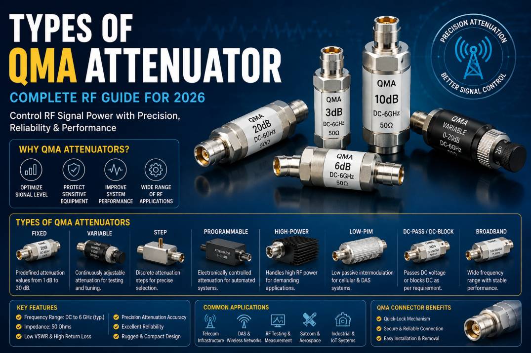
QMA attenuators are important RF components used to control signal power in wireless communication, telecom infrastructure, RF testing, distributed antenna systems, and other high-frequency applications. A QMA attenuator combines the electrical function of an RF attenuator with the mechanical convenience of the QMA connector interface.
An RF attenuator reduces the power level of an RF signal by a specified amount while maintaining the required impedance and minimizing unwanted reflections. QMA connectors are compact quick-lock RF connectors designed for applications where fast installation and removal are beneficial compared with threaded RF interfaces.
Different types of QMA attenuators are available depending on attenuation value, frequency range, power handling, connector gender, impedance, VSWR, PIM performance, environmental requirements, and application.
This guide explains the major types of QMA attenuators, their working principles, specifications, advantages, applications, and selection criteria.
What Is a QMA Attenuator?
A QMA attenuator is an RF attenuating device equipped with QMA connectors. It is designed to reduce the power level of an RF signal by a controlled amount.
For example, if a system contains a 10 dBm signal and a 6 dB QMA attenuator is inserted into the RF path, the ideal output level is approximately 4 dBm, assuming negligible additional system effects.
The basic function of a QMA attenuator is to provide controlled attenuation while maintaining the characteristic impedance of the RF transmission system.
Typical QMA attenuators are designed around 50 ohms, although the exact electrical specifications depend on the product.
Why Are QMA Attenuators Used?
RF systems often require precise signal-level control. Excessive RF power can overload sensitive receiver inputs, test equipment, amplifiers, or other components.
QMA attenuators can be used to:
- Reduce excessive RF power
- Protect sensitive RF equipment
- Improve impedance matching
- Control signal levels
- Reduce receiver overload
- Support RF testing
- Simulate transmission-line losses
- Improve system-level signal management
- Help control interference and unwanted signal levels
- Provide predictable attenuation between RF components
How Does a QMA Attenuator Work?
An RF attenuator uses resistive or other engineered circuit elements to reduce signal power.
In a conventional fixed attenuator, the circuit is designed to provide a specific attenuation value while maintaining the required impedance.
For a 50-ohm system, the attenuator is designed so that the input and output ports remain approximately matched to 50 ohms across its specified frequency range.
The amount of attenuation is expressed in decibels (dB).
Common attenuation values include:
- 1 dB
- 2 dB
- 3 dB
- 5 dB
- 6 dB
- 10 dB
- 15 dB
- 20 dB
- 30 dB
The available values depend on the manufacturer and application.
Main Types of QMA Attenuators
QMA attenuators can be classified according to attenuation mechanism, adjustment method, power capability, RF performance, connector configuration, and application.
The major types include:
- Fixed QMA Attenuator
- Variable QMA Attenuator
- Step QMA Attenuator
- Programmable QMA Attenuator
- High-Power QMA Attenuator
- Low-PIM QMA Attenuator
- Precision QMA Attenuator
- Broadband QMA Attenuator
- DC-Pass QMA Attenuator
- DC-Block QMA Attenuator
- Inline QMA Attenuator
- QMA Male-to-Female Attenuator
- QMA Male-to-Male Attenuator
- QMA Female-to-Female Attenuator
- Outdoor QMA Attenuator
1. Fixed QMA Attenuator
A fixed QMA attenuator provides a predetermined attenuation value that cannot be adjusted during normal operation.
For example, a 3 dB QMA attenuator always provides approximately 3 dB of nominal attenuation within its specified operating conditions.
Common Attenuation Values
- 1 dB
- 2 dB
- 3 dB
- 5 dB
- 6 dB
- 10 dB
- 15 dB
- 20 dB
- 30 dB
Advantages
- Simple design
- Stable attenuation
- Compact construction
- Easy installation
- Reliable RF performance
- Cost-effective for permanent applications
Applications
Fixed QMA attenuators are widely used in:
- RF communication systems
- Wireless infrastructure
- RF test equipment
- Laboratory setups
- Distributed antenna systems
- Signal conditioning
- RF cable assemblies
- Telecom equipment
2. Variable QMA Attenuator
A variable QMA attenuator allows the attenuation level to be adjusted over a defined range.
Unlike a fixed attenuator, a variable design can provide different attenuation levels depending on system requirements.
For example, a variable attenuator may allow the user to adjust attenuation from a low value to a higher specified value.
Applications
Variable QMA attenuators are useful in:
- RF laboratories
- Communication testing
- Signal-level optimization
- Receiver testing
- Transmitter testing
- RF development
- Calibration environments
Advantages
- Adjustable signal level
- Flexible testing
- Useful during RF development
- Can support multiple attenuation requirements
3. Step QMA Attenuator
A step attenuator provides selectable attenuation levels in discrete increments.
Instead of continuously adjusting the attenuation, the user selects predefined steps.
For example, a step attenuator may provide selectable values such as:
0 dB, 1 dB, 2 dB, 4 dB, 8 dB, and 16 dB.
The actual configuration varies by product.
Applications
Step QMA attenuators are commonly used in:
- RF laboratories
- Test benches
- Communication equipment
- Receiver sensitivity testing
- Transmitter characterization
- RF calibration
4. Programmable QMA Attenuator
A programmable attenuator provides electronically controlled attenuation.
The attenuation level can be controlled through an external electrical interface or control system, depending on the design.
Programmable attenuators are particularly useful in automated RF testing and communication systems.
Applications
- Automated test equipment
- RF production testing
- Wireless communication systems
- Research laboratories
- Electronic measurement systems
- Automated signal control
Benefits
- Remote attenuation control
- Repeatable settings
- Automated testing
- Fast signal-level adjustment
- Integration with test systems
5. High-Power QMA Attenuator
High-power QMA attenuators are designed to handle higher RF power levels than standard attenuators.
Power-handling capability depends on factors such as frequency, attenuation value, ambient temperature, cooling conditions, and duty cycle.
Applications
High-power QMA attenuators can be used in:
- RF transmitters
- Telecom infrastructure
- Base-station systems
- RF amplifiers
- Broadcast equipment
- Laboratory transmitters
- Power testing
Important Considerations
The rated power of an attenuator should never be considered independently of frequency and operating conditions.
Manufacturers may specify:
- Average power
- Peak power
- CW power
- Pulse power
- Derating versus temperature
- Frequency-dependent power handling
6. Low-PIM QMA Attenuator
Low-PIM attenuators are designed for wireless infrastructure where passive intermodulation must be minimized.
PIM occurs when unwanted intermodulation products are generated by nonlinear behavior in passive RF components.
Low-PIM QMA attenuators can be useful in cellular networks and distributed antenna systems where very weak receiver signals can be affected by interference.
Applications
- Cellular infrastructure
- DAS systems
- Indoor wireless systems
- Telecom networks
- Public safety communication
- Multi-band wireless infrastructure
Important Features
Low-PIM designs may incorporate:
- Precision-machined components
- Controlled contact surfaces
- High-quality RF materials
- Robust connector interfaces
- Carefully controlled assembly processes
7. Precision QMA Attenuator
Precision QMA attenuators are designed for applications requiring tightly controlled RF characteristics.
These products may provide improved specifications for:
- Attenuation accuracy
- Return loss
- VSWR
- Frequency response
- Power handling
- Connector repeatability
Applications
- RF laboratories
- Calibration systems
- Test and measurement
- Aerospace testing
- Defense electronics
- Communication equipment development
8. Broadband QMA Attenuator
A broadband QMA attenuator is designed to maintain useful attenuation performance over a relatively wide frequency range.
Broadband designs are valuable when one attenuator needs to support multiple RF bands.
Applications
- Multi-band wireless systems
- Telecom infrastructure
- RF test equipment
- Cellular networks
- RF laboratories
- Antenna systems
The exact bandwidth must always be checked against the manufacturer’s datasheet.
9. DC-Pass QMA Attenuator
A DC-pass attenuator allows DC voltage to pass through the RF path while attenuating the RF signal.
This configuration can be useful in systems where DC power needs to travel through a coaxial connection.
Applications
- Active antenna systems
- Bias-powered RF equipment
- RF modules
- Remote amplifier systems
- Antenna systems requiring DC feed
The DC voltage and current ratings must be verified before using the attenuator in a powered RF path.
10. DC-Block QMA Attenuator
A DC-block attenuator prevents DC voltage from passing between its RF ports while providing the specified RF attenuation.
This can help protect equipment from unwanted DC voltage.
Applications
- RF test systems
- Receiver protection
- Signal generators
- RF measurement equipment
- Systems where DC isolation is required
The DC blocking characteristics should be checked alongside the RF specifications.
11. Inline QMA Attenuator
An inline QMA attenuator is designed to be inserted directly into an RF transmission path.
It normally has an RF connector at each end and is installed between two compatible components.
Typical Applications
- RF cables
- Antenna systems
- RF modules
- Test equipment
- Wireless communication equipment
Inline QMA attenuators are particularly convenient when signal-level adjustment is required without redesigning the RF cable assembly.
QMA Attenuator Connector Configurations
QMA attenuators can be supplied in different connector configurations.
Common configurations include:
QMA Male to QMA Female
This configuration is useful when the attenuator needs to be inserted directly between a QMA male and QMA female interface.
QMA Male to QMA Male
A male-to-male configuration can be used where both connected RF interfaces are female.
QMA Female to QMA Female
A female-to-female configuration can be used when both connected RF interfaces are male.
The correct connector configuration should be selected according to the equipment interface and mechanical requirements.
QMA Attenuator Attenuation Values
Attenuation is measured in decibels.
The relationship between input and output power can be expressed as:
Attenuation (dB) = 10 log10(Pin/Pout)
For example, a 10 dB attenuator reduces the output power to approximately one-tenth of the input power.
A 3 dB attenuator reduces power to approximately half of the input level.
| Attenuation | Approximate Output Power |
|---|---|
| 1 dB | 79.4% |
| 2 dB | 63.1% |
| 3 dB | 50.1% |
| 5 dB | 31.6% |
| 6 dB | 25.1% |
| 10 dB | 10.0% |
| 20 dB | 1.0% |
| 30 dB | 0.1% |
These values represent ideal power ratios.
QMA Attenuator Frequency Range
Frequency range is one of the most important specifications when selecting a QMA attenuator.
QMA attenuators may be designed for different RF frequency ranges depending on their construction.
Applications can range from lower-frequency wireless systems to high-frequency RF and microwave applications.
The selected attenuator should support the entire operating frequency range of the system.
Important specifications may include:
- Minimum frequency
- Maximum frequency
- Attenuation flatness
- Return loss
- VSWR
- Insertion loss
- Power handling
QMA Attenuator Impedance
Most QMA RF attenuators are designed for 50-ohm systems.
Maintaining 50-ohm impedance through the RF path helps reduce signal reflections and ensures compatibility with standard RF equipment.
Impedance mismatch can cause:
- Increased reflections
- Higher VSWR
- Reduced signal transfer
- Measurement errors
- Reduced system efficiency
QMA Attenuator VSWR
VSWR, or Voltage Standing Wave Ratio, indicates how well the attenuator is matched to the RF system.
A lower VSWR generally indicates better impedance matching.
High-quality QMA attenuators are designed to provide low VSWR across their specified frequency range.
For precision RF applications, VSWR should be evaluated across the complete operating bandwidth rather than at a single frequency.
QMA Attenuator Return Loss
Return loss indicates the amount of RF power reflected back toward the source.
Higher return loss generally indicates better impedance matching.
A good QMA attenuator should provide appropriate return-loss performance for its intended frequency range and application.
QMA Attenuator Insertion Loss
Insertion loss describes the reduction in signal level caused by inserting a component into an RF path.
An attenuator intentionally reduces signal power by its specified attenuation value. Additional losses may occur because of connector interfaces and internal construction.
When evaluating a QMA attenuator, it is important to distinguish the specified attenuation from other insertion-loss characteristics.
QMA Attenuator Power Rating
Power handling is critical when selecting an RF attenuator.
The required rating depends on:
- Input RF power
- Frequency
- Attenuation value
- Ambient temperature
- Duty cycle
- Pulse characteristics
- Cooling conditions
- Installation environment
For example, an attenuator rated for a particular continuous-wave power level may require derating at elevated temperatures.
Always use the manufacturer’s power-rating specifications.
QMA Attenuator Materials and Construction
QMA attenuators are typically manufactured using precision RF materials and components.
Depending on the design, construction may include:
- Conductive metal bodies
- Precision-machined connectors
- RF resistive elements
- Dielectric materials
- Plated contact surfaces
- Protective housings
Material selection influences electrical performance, durability, thermal performance, corrosion resistance, and connector reliability.
Advantages of QMA Attenuators
QMA attenuators provide several advantages in RF systems.
Quick-Lock Connection
The QMA interface is designed for quick connection and disconnection without requiring the repeated rotation associated with many threaded connector interfaces.
Signal-Level Control
They provide a predictable way to reduce RF power.
Compact Design
QMA components are suitable for systems where space is limited.
Easy Installation
The quick-lock interface can simplify RF assembly and maintenance.
Multiple Attenuation Options
Fixed and adjustable attenuation values can be selected according to application requirements.
Wide Application Range
QMA attenuators can be used in telecom, wireless communication, RF testing, DAS, and other RF systems.
Applications of QMA Attenuators
QMA attenuators are used in many RF and wireless communication applications.
Telecom Infrastructure
They can be used for RF signal-level management in cellular infrastructure.
Distributed Antenna Systems
Low-PIM QMA attenuators can be useful in DAS installations where minimizing passive intermodulation is important.
RF Test and Measurement
Attenuators are frequently used to control signal levels during laboratory measurements.
Wireless Communication
QMA attenuators can help manage RF power levels between antennas, radios, amplifiers, and other components.
RF Amplifier Testing
An attenuator can reduce the output level from an amplifier before connecting it to sensitive measurement equipment.
Receiver Protection
Appropriately rated attenuation can help prevent excessive RF power from reaching sensitive receiver inputs.
Antenna Systems
QMA attenuators can be integrated into antenna feeder systems to achieve a required RF signal level.
Aerospace and Defense
Precision RF attenuators are used in various test and communication systems where controlled RF performance is required.
QMA Attenuator vs SMA Attenuator
QMA and SMA attenuators can perform similar electrical functions, but their connector interfaces are different.
| Feature | QMA Attenuator | SMA Attenuator |
|---|---|---|
| Connector mechanism | Quick-lock | Threaded |
| Typical impedance | 50 ohms | 50 ohms |
| Connection | Quick installation | Screw-on |
| Application | Telecom and wireless | General RF and microwave |
| Maintenance | Convenient | Requires threading |
| Compact RF systems | Suitable | Suitable |
The choice between QMA and SMA depends on the equipment interface, installation requirements, frequency range, mechanical design, and application.
QMA Attenuator vs QMA Adapter
A QMA attenuator and QMA adapter perform different functions.
A QMA adapter changes the connector interface or gender configuration.
A QMA attenuator reduces RF signal power by a defined amount.
For example, an adapter may connect two different RF interfaces, while a 10 dB QMA attenuator reduces the RF power level by approximately 10 dB.
QMA Attenuator vs Termination
An RF termination absorbs RF power at the end of a transmission line, while an attenuator is installed inline to reduce signal power while allowing the RF signal to continue through the transmission path.
QMA Attenuator
- Inline component
- Has input and output ports
- Reduces signal power
- Used for signal-level control
QMA Termination
- Usually a single-port device
- Absorbs RF energy
- Used to terminate unused ports
- Helps prevent reflections
QMA Attenuator Selection Guide
Selecting the correct QMA attenuator requires evaluating several parameters.
Frequency
Choose an attenuator that covers the complete operating frequency range.
Attenuation
Determine the required reduction in RF power.
Power Handling
Select a suitable power rating with appropriate safety margin and derating considerations.
Connector Configuration
Check QMA male and female interfaces.
VSWR
Choose a device with suitable VSWR across the required bandwidth.
Return Loss
Verify return-loss specifications when low-reflection performance is important.
PIM
For cellular and DAS applications, consider a low-PIM design where required.
Environmental Conditions
For outdoor systems, check:
- Operating temperature
- Weather resistance
- Corrosion resistance
- Mechanical strength
- Sealing requirements
Physical Dimensions
Verify that the attenuator fits within the available installation space.
Common QMA Attenuator Selection Mistakes
Choosing the Wrong Frequency Range
An attenuator may provide excellent performance at one frequency but unsuitable performance outside its specified bandwidth.
Ignoring Power Rating
Operating beyond the specified power rating can cause excessive heating and permanent component damage.
Selecting the Wrong Connector Gender
Always check both sides of the RF connection before ordering.
Ignoring PIM Requirements
Standard attenuators may not be suitable for applications where passive intermodulation performance is critical.
Using Excessive Attenuation
Too much attenuation can reduce the signal below the desired operating level.
Ignoring Environmental Requirements
Outdoor installations require appropriate environmental protection and mechanical durability.
QMA Attenuator Testing
Professional QMA attenuators can be evaluated using RF test equipment such as:
- Vector Network Analyzers
- Signal generators
- Spectrum analyzers
- RF power meters
- Network analyzers
Common measurements include:
- Insertion loss
- Attenuation accuracy
- Return loss
- VSWR
- Frequency response
- Power handling
- PIM performance
- Isolation
For precision applications, calibration and appropriate test fixtures are important for obtaining reliable measurements.
QMA Attenuator for RF Test and Measurement
RF laboratories often use attenuators to control signal levels and protect measurement instruments.
Applications include:
- Signal generator testing
- Receiver sensitivity testing
- VNA measurements
- RF amplifier testing
- Spectrum analyzer protection
- RF system calibration
- Cable testing
Fixed precision attenuators are particularly useful when repeatable signal reduction is required.
QMA Attenuator for Telecom Applications
QMA connectors are useful in telecom environments where fast connection and disconnection can be beneficial.
QMA attenuators can be used in:
- Cellular infrastructure
- DAS
- Indoor wireless systems
- RF distribution networks
- Base-station equipment
- RF feeder systems
For cellular applications, low-PIM specifications can be particularly important.
QMA Attenuator for High-Frequency Applications
High-frequency RF applications require careful attention to connector geometry, material selection, impedance control, and manufacturing tolerances.
At higher frequencies, even small mechanical imperfections can influence RF performance.
Important parameters include:
- Frequency response
- VSWR
- Return loss
- Connector quality
- Attenuation flatness
- Mechanical repeatability
QMA Attenuator Maintenance
QMA attenuators generally require limited maintenance when correctly installed.
However, users should periodically inspect:
- Connector condition
- RF interface cleanliness
- Mechanical damage
- Corrosion
- Loose connections
- Cable stress
- Environmental damage
Contamination or physical damage to RF interfaces can affect electrical performance.
Future Trends in QMA Attenuator Technology
RF communication systems continue to demand compact, reliable, broadband, and high-performance passive components.
Important trends include:
- Higher-frequency operation
- Broadband RF performance
- Low-PIM designs
- Higher power handling
- Smaller form factors
- Improved connector durability
- Precision attenuation
- Multi-band telecom applications
- Advanced RF test systems
- Ruggedized outdoor components
As wireless networks become more complex, reliable RF signal-level control remains essential for maintaining system performance.
Conclusion
QMA attenuators are versatile RF components designed to provide controlled signal attenuation while offering the quick-lock convenience of the QMA connector interface.
The most common types include fixed, variable, step, programmable, high-power, low-PIM, precision, broadband, DC-pass, DC-block, and inline QMA attenuators. Each type serves a different purpose and should be selected according to the RF system requirements.
Frequency range, attenuation value, impedance, VSWR, return loss, power rating, PIM performance, connector configuration, environmental conditions, and physical dimensions are important parameters when choosing a QMA attenuator.
For telecom infrastructure, DAS, RF testing, wireless communication, and other high-frequency applications, selecting the correct QMA attenuator can provide reliable signal-level control and improve overall RF system performance.
Frequently Asked Questions
1. What is a QMA attenuator?
A QMA attenuator is an RF component that reduces signal power by a specified amount while using QMA connectors for quick-lock RF connections.
2. What are the main types of QMA attenuators?
The main types include fixed, variable, step, programmable, high-power, low-PIM, precision, broadband, DC-pass, DC-block, and inline QMA attenuators.
3. What is a fixed QMA attenuator?
A fixed QMA attenuator provides a predetermined attenuation value such as 3 dB, 6 dB, 10 dB, or 20 dB and does not normally allow adjustment during operation.
4. What is a variable QMA attenuator?
A variable QMA attenuator allows the attenuation level to be adjusted across a specified range, making it useful for RF testing and signal optimization.
5. What is a low-PIM QMA attenuator?
A low-PIM QMA attenuator is designed to minimize passive intermodulation and is suitable for applications such as cellular infrastructure and distributed antenna systems.
6. What impedance is commonly used for QMA attenuators?
Most QMA attenuators are designed for 50-ohm RF systems.
7. What attenuation values are available in QMA attenuators?
Common values include 1 dB, 2 dB, 3 dB, 5 dB, 6 dB, 10 dB, 15 dB, 20 dB, and 30 dB, although availability varies by manufacturer.
8. What is the difference between a QMA attenuator and a QMA adapter?
A QMA attenuator reduces RF signal power, while a QMA adapter changes or connects different RF connector interfaces.
9. What is the difference between a QMA attenuator and a termination?
An attenuator is an inline two-port component that reduces signal power, whereas a termination is generally a one-port component designed to absorb RF power at the end of a transmission line.
10. Are QMA attenuators suitable for telecom applications?
Yes. QMA attenuators can be used in telecom infrastructure, cellular systems, DAS, RF distribution systems, and other wireless communication applications.
11. What is a high-power QMA attenuator?
A high-power QMA attenuator is designed to dissipate higher levels of RF power than standard attenuators. Its actual power rating depends on frequency, temperature, duty cycle, and product design.
12. Why is VSWR important in a QMA attenuator?
VSWR indicates how well the attenuator is impedance matched to the RF system. Lower VSWR generally indicates better matching and lower reflected power.
13. What is a broadband QMA attenuator?
A broadband QMA attenuator is designed to maintain its specified attenuation and RF characteristics across a relatively wide frequency range.
14. Can QMA attenuators be used for RF testing?
Yes. QMA attenuators are useful in RF test systems for signal-level control, receiver testing, amplifier testing, calibration, and protecting measurement equipment.
15. How do I choose the right QMA attenuator?
Consider the required frequency range, attenuation value, power rating, impedance, VSWR, return loss, connector configuration, PIM requirements, environmental conditions, and physical dimensions.
16. What does a 10 dB QMA attenuator do?
Ideally, a 10 dB attenuator reduces RF power to approximately one-tenth of its input power.
17. What connectors are used with QMA attenuators?
QMA attenuators use QMA interfaces and can be supplied in different gender configurations, such as QMA male-to-female, male-to-male, or female-to-female.
18. Can QMA attenuators handle high frequencies?
Yes. QMA attenuators are available for various RF frequency ranges, but the maximum operating frequency must always be confirmed from the specific product datasheet.
19. Why is power handling important for QMA attenuators?
Power handling determines how much RF energy the attenuator can safely dissipate. Exceeding the specified rating can cause excessive heating or component failure.
20. Where are QMA attenuators commonly used?
QMA attenuators are used in telecom infrastructure, cellular networks, DAS, RF laboratories, test and measurement equipment, wireless communication systems, antenna networks, and RF signal-conditioning applications.










