
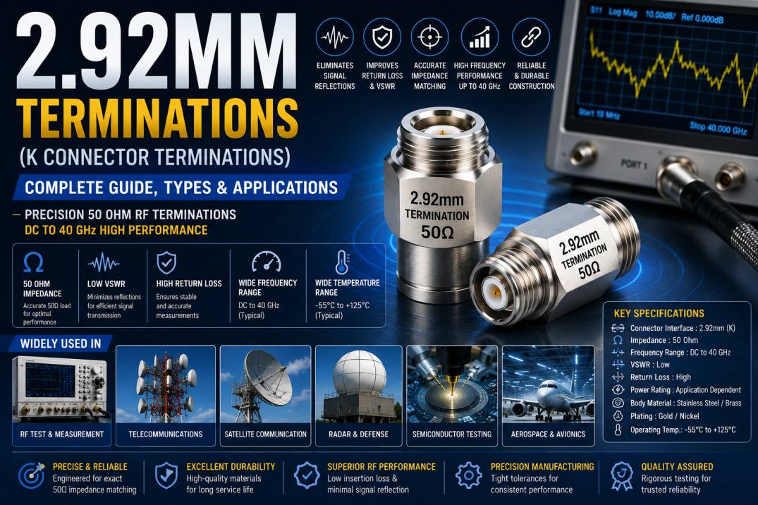
2.92mm Terminations are precision RF components designed to provide a controlled 50 Ohm load at the end of a high-frequency transmission line. They are widely used in microwave and millimeter-wave testing, telecommunications, aerospace, defense, radar, satellite communication, semiconductor testing, and advanced RF measurement applications.
The 2.92mm interface is commonly known as the K connector. It was developed for high-frequency applications where conventional RF connectors may not provide the required electrical performance. Depending on the design and manufacturer, 2.92mm components are commonly specified for operation up to approximately 40 GHz.
A 2.92mm RF Termination contains a precision resistive element that absorbs incoming RF energy and minimizes unwanted reflections. By maintaining a controlled 50 Ohm impedance, the termination helps reduce VSWR and improve measurement accuracy.
Because high-frequency systems are highly sensitive to impedance discontinuities, precision 2.92mm Terminations are particularly important in professional RF test and measurement environments.
What Is a 2.92mm Termination?
A 2.92mm Termination is a 50 Ohm RF termination fitted with a 2.92mm coaxial connector interface. Its primary purpose is to terminate an RF transmission path and absorb the signal energy instead of allowing the signal to reflect back toward the source.
When a transmission line is properly terminated with a load that matches its characteristic impedance, signal reflections are minimized.
For a typical 50 Ohm RF system:
- Transmission line impedance: 50 Ohm
- Termination impedance: 50 Ohm
- Connector interface: 2.92mm
- Typical frequency capability: DC to 40 GHz, depending on design
- Primary purpose: RF signal absorption and impedance matching
The precision of the termination becomes increasingly important as frequency increases.
Why Are 2.92mm Terminations Important?
At microwave frequencies, even small impedance discontinuities can create measurable signal reflections. These reflections can affect RF measurements, increase VSWR, and reduce the accuracy of system characterization.
A properly designed 2.92mm Termination provides a controlled electrical environment and helps:
- Minimize signal reflections
- Maintain 50 Ohm impedance
- Reduce VSWR
- Improve return loss
- Improve RF measurement accuracy
- Provide a stable reference load
- Protect unused RF ports
- Improve test repeatability
- Reduce impedance discontinuities
- Maintain high-frequency signal integrity
For professional RF laboratories, precision termination components are essential for obtaining consistent and reliable results.
How Does a 2.92mm Termination Work?
The basic working principle is impedance matching.
When an RF signal travels through a 50 Ohm coaxial cable and reaches a 50 Ohm termination, most of the signal energy is absorbed by the termination’s resistive element.
If the load impedance does not match the transmission line, a portion of the signal is reflected toward the source.
Signal reflection can result in:
- Increased VSWR
- Lower return loss
- Standing waves
- Measurement uncertainty
- Reduced power transfer
- Unwanted interference
The precision resistor inside the 2.92mm termination converts RF energy into heat, creating a controlled load at the end of the transmission line.
What Is the Impedance of a 2.92mm Termination?
Most 2.92mm Terminations are designed with a nominal impedance of 50 Ohms.
50 Ohm impedance is widely used in RF and microwave systems because it provides a practical balance between power handling and signal loss.
50 Ohm 2.92mm Terminations are commonly used with:
- Vector Network Analyzers
- Spectrum Analyzers
- Signal Generators
- RF Power Meters
- Microwave Test Equipment
- RF Test Fixtures
- Microwave Modules
- High-Frequency Cable Assemblies
Using a termination with the correct impedance is critical for maintaining system performance.
2.92mm Termination Frequency Range
The 2.92mm connector interface is designed for high-frequency applications and is commonly associated with operation up to approximately 40 GHz.
The actual frequency capability of a termination depends on its construction, connector geometry, resistive element, materials, manufacturing tolerances, and electrical specifications.
Typical applications include:
- DC to 18 GHz
- DC to 26.5 GHz
- DC to 40 GHz
Specialized products may have different frequency specifications.
For high-frequency applications, engineers should always verify the manufacturer’s specified frequency range rather than selecting a termination based only on the connector name.
Construction of a 2.92mm RF Termination
A precision 2.92mm Termination consists of several carefully engineered components.
2.92mm Connector Body
The connector body provides mechanical support and maintains the required coaxial geometry.
Center Contact
The center contact carries the RF signal into the resistive load and must provide reliable electrical conductivity.
Precision Resistor
The resistor provides the controlled 50 Ohm load and absorbs the incoming RF energy.
Dielectric Insulator
The dielectric maintains controlled spacing between the center conductor and outer conductor.
Outer Conductor
The outer conductor provides the RF return path and contributes to electromagnetic shielding.
Connector Plating
High-quality plating improves conductivity, corrosion resistance, mechanical durability, and connector reliability.
Key Features of 2.92mm Terminations
High-performance 2.92mm Terminations are designed to provide stable electrical and mechanical characteristics at high frequencies.
50 Ohm Impedance
The standard 50 Ohm impedance makes these terminations suitable for most microwave and RF test systems.
High-Frequency Performance
2.92mm Terminations are designed for demanding applications that can extend into the millimeter-wave frequency range.
Low VSWR
A low VSWR indicates better impedance matching and reduced signal reflection.
High Return Loss
High return loss indicates that less incident RF energy is reflected toward the source.
Precision Mechanical Geometry
Accurate connector dimensions help maintain predictable electrical performance at high frequencies.
Excellent Shielding
The coaxial construction helps reduce electromagnetic leakage and external interference.
Compact Design
The 2.92mm interface provides a compact solution for dense microwave test systems.
High Repeatability
Precision manufacturing allows stable performance during repeated measurements and connections.
Technical Specifications of 2.92mm Terminations
Typical specifications for a precision 2.92mm Termination may include:
- Connector Interface: 2.92mm
- Connector Type: Male or Female
- Impedance: 50 Ohm
- Frequency Range: DC to 40 GHz, depending on design
- VSWR: Low VSWR
- Return Loss: High return loss
- Body Material: Stainless steel, brass, or other RF-grade materials
- Contact Material: Copper alloy or conductive RF material
- Plating: Gold, nickel, or other suitable plating
- Insulator: PTFE or high-performance dielectric
- Operating Temperature: Application dependent
- Power Rating: Application and frequency dependent
Exact specifications vary according to the product design and manufacturer.
Types of 2.92mm Terminations
2.92mm Terminations can be classified based on connector configuration, electrical performance, and intended application.
2.92mm Male Termination
A 2.92mm Male Termination is designed to connect with a compatible female RF interface.
It is commonly used with:
- RF test cables
- Microwave instruments
- Test fixtures
- VNA ports
- RF modules
2.92mm Female Termination
A 2.92mm Female Termination is designed for applications requiring a female 2.92mm interface.
It can be used on:
- RF equipment
- Microwave test fixtures
- RF modules
- Measurement systems
- Laboratory test setups
Precision 2.92mm Termination
Precision versions are manufactured with tight dimensional tolerances and are intended for demanding measurement applications where VSWR and return loss are critical.
High-Power 2.92mm Termination
High-power terminations are designed to handle greater RF power levels while maintaining acceptable electrical performance.
Power handling must always be evaluated at the actual operating frequency and temperature.
2.92mm Terminations and K Connector Terminations
The 2.92mm connector is commonly referred to as a K connector. As a result, products are often marketed using terms such as:
- 2.92mm RF Termination
- 2.92mm Termination
- K Connector Termination
- K-Type RF Termination
- 40 GHz RF Termination
- 2.92mm 50 Ohm Termination
These terms can refer to the same general connector family, although the exact electrical specifications depend on the individual product.
2.92mm Terminations vs SMA Terminations
SMA and 2.92mm connectors have similar mechanical characteristics, but they are designed for different levels of high-frequency performance.
SMA connectors are widely used in general RF and microwave applications. 2.92mm connectors are designed for higher-frequency applications and are commonly used in precision systems operating up to around 40 GHz.
A 2.92mm termination may therefore be preferred when:
- Higher-frequency performance is required
- Lower VSWR is important
- Precision measurements are being performed
- Microwave test equipment operates near the upper SMA range
2.92mm Terminations vs 3.5mm Terminations
3.5mm connectors are widely used in precision microwave systems and can provide excellent electrical performance.
2.92mm connectors are commonly selected for applications extending to higher frequencies, often around 40 GHz.
The selection should be based on:
- Frequency range
- VSWR
- Return loss
- Mechanical compatibility
- Power requirements
- Test equipment interface
- Measurement accuracy
2.92mm Terminations vs 2.4mm Terminations
2.4mm and 2.92mm interfaces are both designed for high-frequency RF applications, but they target different performance ranges.
2.92mm interfaces are commonly used for applications up to approximately 40 GHz, while 2.4mm interfaces are often selected for higher-frequency applications.
The correct termination should always match the interface and frequency requirements of the test system.
Applications of 2.92mm Terminations
2.92mm Terminations are widely used in advanced RF and microwave applications.
RF Test and Measurement
They are commonly used to terminate unused ports on RF and microwave test equipment.
Applications include:
- RF cable testing
- Connector testing
- Filter testing
- Amplifier testing
- RF module characterization
- Microwave component measurements
Vector Network Analyzers
VNAs require accurate impedance environments for reliable S-parameter measurements.
2.92mm Terminations can be used as controlled loads during calibration and testing.
Spectrum Analyzers
A properly rated 2.92mm termination can provide a controlled load for high-frequency measurement setups and unused RF ports.
Signal Generators
2.92mm terminations can be used to provide a matched load at the output of high-frequency signal generators.
Aerospace Applications
Aerospace electronics often require compact, high-performance RF components capable of operating across demanding frequency ranges.
Defense Electronics
Radar, communication, electronic warfare, and other defense systems rely on precision RF and microwave components.
Radar Systems
Radar systems operate at microwave and millimeter-wave frequencies where impedance matching and low reflection are important.
Satellite Communication
Satellite RF systems require accurate signal transmission and reliable high-frequency components.
Semiconductor Testing
High-speed semiconductor devices require sophisticated RF characterization equipment. 2.92mm Terminations can be used in semiconductor test fixtures and measurement systems.
Telecommunications
Advanced wireless and high-frequency communication systems use precision RF components for testing, development, and validation.
Research and Development
Universities, research laboratories, and engineering organizations use 2.92mm components for microwave and millimeter-wave experimentation.
Benefits of Using 2.92mm Terminations
Improved Signal Integrity
Proper impedance matching minimizes unwanted signal reflections and helps maintain clean RF transmission.
Reduced VSWR
A precision 50 Ohm termination reduces the mismatch between the transmission line and load.
Better Measurement Accuracy
Controlled impedance improves the reliability and repeatability of RF measurements.
High-Frequency Capability
2.92mm Terminations are suitable for demanding microwave applications extending toward the millimeter-wave range.
Equipment Protection
A correctly rated termination provides a controlled load for RF ports and helps avoid unintended open-circuit conditions.
Consistent Test Results
Precision construction allows repeatable measurements across different test sessions.
Compact Construction
The small form factor is useful for high-density RF test systems and compact microwave assemblies.
Understanding VSWR in 2.92mm Terminations
VSWR, or Voltage Standing Wave Ratio, is one of the key parameters used to evaluate RF impedance matching.
When an RF transmission line is terminated with its characteristic impedance, reflections are minimized and VSWR approaches its ideal value of 1:1.
A higher VSWR indicates greater mismatch and therefore greater reflected energy.
For precision 2.92mm Terminations, engineers generally look for low VSWR across the complete operating frequency range.
Understanding Return Loss
Return loss measures the amount of RF signal power reflected back toward the source.
A higher return loss generally indicates better impedance matching.
For high-frequency applications, return loss should be evaluated across the required frequency range rather than at only one test frequency.
A termination with excellent return loss can provide a more stable load and improve the accuracy of RF measurements.
Power Handling of 2.92mm Terminations
Power handling is an important specification when selecting a 2.92mm Termination.
The maximum permissible power depends on:
- Operating frequency
- Resistor technology
- Connector construction
- Thermal design
- Ambient temperature
- RF signal duration
- Duty cycle
A termination may have a different power rating at different frequencies.
Engineers should therefore use the manufacturer’s power derating information when operating near the maximum rated power.
How to Choose the Right 2.92mm Termination
Selecting the correct termination requires evaluation of several specifications.
Check the Frequency Range
Select a termination that supports the maximum operating frequency of the system.
Verify the Impedance
For standard RF and microwave applications, ensure that the termination provides a 50 Ohm load.
Check Connector Gender
Select male or female according to the RF port that needs to be terminated.
Evaluate VSWR
For precision measurements, select a termination with low VSWR across the required frequency range.
Check Return Loss
Higher return loss is generally preferred for precision RF measurement applications.
Check Power Rating
Make sure the termination can safely dissipate the expected RF power.
Consider Operating Temperature
For aerospace, defense, industrial, and outdoor applications, check the specified operating temperature.
Check Mechanical Compatibility
Ensure that the connector interface and mating mechanism are compatible with the equipment.
Common Mistakes When Using 2.92mm Terminations
Several mistakes can reduce the performance of high-frequency termination systems.
Common mistakes include:
- Using a termination outside its specified frequency range
- Applying excessive RF power
- Using the wrong connector interface
- Ignoring VSWR specifications
- Ignoring return loss
- Using a damaged termination
- Contaminating the mating interface
- Applying excessive torque
- Failing to inspect connectors
- Using incompatible RF adapters
At frequencies approaching 40 GHz, even small mechanical imperfections can significantly affect electrical performance.
Proper Handling and Maintenance of 2.92mm Terminations
Precision RF connectors should be handled carefully.
Keep the mating surfaces clean and free from dust, oil, moisture, and other contaminants.
Use suitable protective caps when the termination is not installed.
Avoid unnecessary mating cycles because connector wear can gradually affect RF performance.
When connecting the termination, use the manufacturer’s recommended torque procedure. Excessive torque can damage the connector, while insufficient torque may result in unreliable electrical contact.
For laboratory applications, periodic inspection and electrical verification are recommended.
Why Precision Manufacturing Matters
At high frequencies, connector geometry becomes a major factor in electrical performance.
Small dimensional variations in the center conductor, dielectric, or outer conductor can introduce impedance discontinuities.
Precision manufacturing helps control:
- Connector dimensions
- Coaxial geometry
- Impedance
- VSWR
- Return loss
- Contact resistance
- Mechanical alignment
- Repeatability
For this reason, high-quality 2.92mm Terminations require precision machining, controlled materials, accurate plating, and strict quality inspection.
2.92mm Terminations for VNA Calibration
One of the most important uses of precision 2.92mm Terminations is vector network analyzer calibration.
During VNA calibration, known standards such as open, short, load, and through standards are used to establish a measurement reference plane.
A precision 50 Ohm load provides a controlled impedance reference for the calibration process.
The quality of the termination directly affects the accuracy of high-frequency measurements, particularly when operating close to the upper frequency limit of the test system.
2.92mm Terminations in Microwave Test Systems
Modern microwave test systems require accurate and repeatable RF connections.
2.92mm Terminations can be used in:
- Microwave test fixtures
- RF cable assemblies
- Calibration kits
- Automated test equipment
- RF switching systems
- Antenna measurement systems
- High-frequency component testing
Their compact size and high-frequency capability make them suitable for advanced test environments.
Quality Considerations for 2.92mm Terminations
When purchasing 2.92mm Terminations, engineers should evaluate more than just the connector size.
Important quality parameters include:
- Impedance accuracy
- Frequency range
- VSWR
- Return loss
- Power handling
- Connector plating
- Mechanical construction
- Temperature range
- Mating durability
- Electrical test data
A reliable manufacturer should provide clear product specifications and test information.
Advantages of High-Quality 2.92mm Terminations
High-quality 2.92mm Terminations provide:
- Accurate 50 Ohm impedance
- Stable high-frequency performance
- Low VSWR
- Excellent return loss
- Reliable RF signal absorption
- Precision mechanical construction
- Good connector durability
- Consistent measurement results
- Wide application compatibility
- Long service life
For professional RF and microwave laboratories, precision termination components can improve both measurement accuracy and system reliability.
Conclusion
2.92mm Terminations are precision 50 Ohm RF components designed to absorb unwanted RF energy and minimize signal reflections in high-frequency transmission systems. Also commonly associated with K connector technology, they are widely used in microwave testing, VNA calibration, telecommunications, aerospace, defense, radar, satellite communication, semiconductor testing, and RF research.
Their ability to maintain controlled impedance, low VSWR, and high return loss makes them particularly useful in precision measurement environments operating up to approximately 40 GHz, depending on the specific product design.
When selecting a 2.92mm Termination, engineers should consider frequency range, impedance, connector gender, VSWR, return loss, power rating, operating temperature, mechanical compatibility, and application requirements.
Choosing a precision-engineered 2.92mm Termination helps maintain signal integrity, reduce unwanted reflections, improve measurement repeatability, and achieve dependable performance in demanding RF and microwave applications.
Frequently Asked Questions About 2.92mm Terminations
What is a 2.92mm Termination?
A 2.92mm Termination is a precision RF load with a 2.92mm coaxial connector interface. It typically provides a 50 Ohm load for microwave and high-frequency RF applications.
What is the impedance of a 2.92mm Termination?
Most 2.92mm Terminations are designed for a nominal 50 Ohm impedance.
What frequency can a 2.92mm Termination support?
Many 2.92mm Terminations are designed for frequencies up to approximately 40 GHz, although the exact frequency range depends on the specific design and manufacturer.
Why is a 2.92mm Termination called a K connector termination?
The 2.92mm connector is commonly known as a K connector, so RF loads using this interface are often called K Connector Terminations or K-Type Terminations.
Are 2.92mm Terminations suitable for VNA testing?
Yes. Precision 2.92mm Terminations are widely used in Vector Network Analyzer testing and calibration applications where accurate impedance matching is required.
What is the difference between a 2.92mm and SMA Termination?
2.92mm Terminations are designed for higher-frequency applications than many standard SMA components and are commonly used in precision microwave systems operating up to around 40 GHz.
What is the difference between 2.92mm and 2.4mm Terminations?
2.92mm interfaces are commonly used up to approximately 40 GHz, while 2.4mm interfaces are generally selected for higher-frequency applications. The correct choice depends on the frequency, interface, and performance requirements.
Why is low VSWR important in a 2.92mm Termination?
Low VSWR indicates good impedance matching and reduced signal reflection. This is especially important for high-frequency RF measurements.
What is return loss in a 2.92mm Termination?
Return loss indicates how much RF energy is reflected back toward the signal source. Higher return loss generally represents better impedance matching.
Can 2.92mm Terminations handle high RF power?
Some 2.92mm Terminations are designed for higher power levels, but the actual power capability depends on frequency, thermal conditions, construction, and the specific manufacturer’s rating.
Where are 2.92mm Terminations used?
They are used in RF laboratories, microwave test systems, VNA calibration, aerospace, defense, radar, satellite communication, telecommunications, semiconductor testing, and high-frequency research.
Are 2.92mm Terminations available in male and female versions?
Yes. 2.92mm Terminations are available in male and female configurations to match different RF equipment and test-system interfaces.
How should a 2.92mm Termination be maintained?
Keep the connector interface clean, use protective caps when not installed, avoid excessive torque, inspect the mating surfaces regularly, and follow the manufacturer’s recommended handling procedures.
How do I choose the right 2.92mm Termination?
Consider the required frequency range, 50 Ohm impedance, connector gender, VSWR, return loss, power rating, temperature range, mechanical requirements, and intended RF application.










