
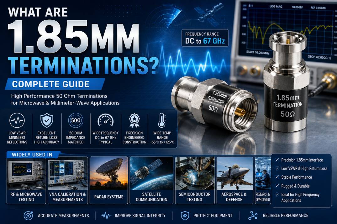
1.85mm Terminations are precision RF components designed to provide a controlled 50 Ohm load at the end of high-frequency transmission lines, test ports, and microwave circuits. They are specifically engineered for very high-frequency applications where conventional RF terminations may not provide sufficient electrical performance.
The 1.85mm connector interface is one of the high-frequency coaxial interfaces used in microwave and millimeter-wave systems. Its small physical geometry supports operation into the millimeter-wave frequency range, making 1.85mm terminations particularly valuable for advanced RF testing, aerospace and defense electronics, radar, satellite communication, semiconductor testing, and high-frequency research.
A properly designed 1.85mm termination absorbs RF energy and minimizes signal reflections. This helps maintain impedance matching, reduce VSWR, improve measurement accuracy, and protect sensitive RF test equipment.
For high-frequency measurement systems, the quality of the termination becomes increasingly important because even small dimensional variations, connector discontinuities, or material imperfections can affect electrical performance.
What Is a 1.85mm Termination?
A 1.85mm termination is a precision 50 Ohm RF load fitted with a 1.85mm coaxial connector interface. It is connected to an RF port or transmission line when a matched load is required.
The primary purpose of a termination is to absorb RF power instead of allowing the signal to reflect from an unterminated port.
A typical 1.85mm termination consists of a precision resistor or resistive structure, coaxial transmission-line geometry, dielectric support, center conductor, outer conductor, and precision-machined connector body.
Because 1.85mm interfaces are designed for extremely high-frequency operation, their dimensions and mechanical tolerances must be carefully controlled.
Why Are 1.85mm Terminations Important?
At microwave and millimeter-wave frequencies, impedance discontinuities can have a significant effect on system performance.
An open or incorrectly terminated RF port can cause:
- Signal reflections
- Increased VSWR
- Reduced return loss
- Measurement errors
- Standing-wave formation
- Power delivery problems
- Unwanted interference
- Reduced system accuracy
A precision 1.85mm termination provides a controlled load that absorbs incident RF energy and minimizes reflections.
This makes it particularly useful in high-frequency test and measurement environments where accurate and repeatable results are essential.
How Does a 1.85mm Termination Work?
The basic principle is impedance matching.
A 1.85mm termination is designed to present a 50 Ohm load to the RF transmission line. When the transmission line and termination have the same characteristic impedance, maximum power transfer occurs with minimal reflection.
The incoming RF signal reaches the termination and is absorbed by the internal resistive element.
Instead of reflecting back toward the source, most of the signal energy is dissipated as heat.
This produces a stable RF environment for measurement and testing.
What Does 1.85mm Mean?
The term 1.85mm refers to the nominal interface size associated with this precision coaxial connector family.
The 1.85mm interface was developed for very high-frequency applications and is closely related in concept to other precision microwave interfaces such as 2.4mm and 2.92mm connectors.
The 1.85mm interface is particularly important for applications extending into the millimeter-wave region.
Its compact geometry reduces electrical discontinuities and supports high-frequency signal transmission when properly manufactured and assembled.
1.85mm Termination Impedance
Most 1.85mm RF terminations are designed with a characteristic impedance of 50 Ohms.
Maintaining 50 Ohm impedance throughout the connector and termination is critical for high-frequency performance.
Impedance consistency helps minimize:
- Reflections
- VSWR
- Return loss degradation
- Measurement uncertainty
- Signal distortion
For this reason, 1.85mm terminations are normally selected according to the impedance of the complete RF system.
Frequency Range of 1.85mm Terminations
One of the major advantages of 1.85mm terminations is their ability to support very high-frequency applications.
Depending on the design and manufacturer, precision 1.85mm terminations can support frequencies extending into the millimeter-wave range, with specialized products commonly specified for operation up to approximately 67 GHz.
The actual usable frequency should always be verified from the manufacturer’s datasheet because performance depends on:
- Connector design
- Manufacturing tolerances
- Internal resistor technology
- VSWR specification
- Return loss
- Power rating
- Calibration requirements
Key Features of 1.85mm Terminations
High-quality 1.85mm terminations typically provide:
- 50 Ohm impedance
- High-frequency operation
- Low VSWR
- Excellent return loss
- Precision mechanical construction
- High-quality RF materials
- Low reflection characteristics
- Compact coaxial design
- Excellent repeatability
- High-frequency measurement capability
- Reliable connector mating
- Stable electrical performance
Technical Specifications of 1.85mm Terminations
Typical specifications may include:
- Connector Type: 1.85mm
- Impedance: 50 Ohm
- Frequency Range: DC to 67 GHz, depending on model
- Connector Gender: Male or Female, depending on configuration
- VSWR: Low VSWR design
- Return Loss: High return loss
- Body Material: Precision-machined metal
- Center Contact: Gold-plated or high-performance conductive material
- Insulator: Low-loss dielectric material
- Operating Temperature: Application dependent
- Power Rating: Application and frequency dependent
Exact specifications vary between products, so the manufacturer’s datasheet should always be consulted before selecting a termination for a critical RF application.
1.85mm Male Terminations
A 1.85mm male termination is designed to connect to a compatible 1.85mm female RF interface.
It is commonly used with:
- RF test equipment
- Microwave instruments
- VNA test ports
- Calibration systems
- High-frequency cable assemblies
- Millimeter-wave modules
The connector geometry must be precisely manufactured to ensure reliable electrical and mechanical performance.
1.85mm Female Terminations
A 1.85mm female termination connects to a compatible 1.85mm male interface.
Female terminations are useful for terminating male RF ports and test fixtures.
They are commonly found in:
- Microwave test systems
- Semiconductor testing
- RF modules
- Laboratory equipment
- High-frequency instrumentation
- Aerospace test systems
1.85mm Terminations for VNA Applications
Vector Network Analyzers are widely used for measuring RF and microwave parameters such as:
- S-parameters
- Return loss
- Insertion loss
- VSWR
- Reflection coefficient
- Phase
- Group delay
A precision 1.85mm termination can be used as a known matched load during calibration and measurement.
The quality of the termination directly affects measurement confidence. Poorly matched loads can introduce errors into calibration and measurement results.
For advanced VNA measurements, precision terminations are therefore an important part of the RF calibration chain.
1.85mm Terminations in RF Calibration
Calibration is one of the most important applications of precision RF terminations.
During calibration, measurement equipment establishes reference conditions for determining the behavior of a device under test.
A high-quality termination provides a known impedance reference.
This helps improve:
- Measurement repeatability
- Calibration accuracy
- Reflection measurements
- Return-loss measurements
- System stability
In demanding microwave and millimeter-wave laboratories, precision calibration components are essential.
Applications of 1.85mm Terminations
RF and Microwave Testing
1.85mm terminations are widely used in advanced RF and microwave test systems where high-frequency performance is required.
Millimeter-Wave Testing
Their compact precision interface makes them suitable for millimeter-wave measurement environments.
Aerospace and Defense
They are used in radar, electronic warfare, satellite payloads, communication systems, and aerospace electronics testing.
Semiconductor Testing
High-frequency semiconductor devices require precise RF measurement environments. 1.85mm components can be used in fixtures and test setups for advanced semiconductor characterization.
Radar Systems
Radar systems operate at high frequencies where reflections and impedance mismatches can significantly affect measurements.
Satellite Communication
1.85mm terminations can be used in high-frequency satellite communication test equipment and RF modules.
Research Laboratories
Universities, research organizations, and advanced RF laboratories use precision millimeter-wave components for experimental systems.
RF Test Fixtures
1.85mm terminations can be integrated into high-frequency fixtures to provide matched loads during device characterization.
Network Analyzer Calibration
They can serve as precision load standards in compatible high-frequency calibration systems.
Advantages of 1.85mm Terminations
Excellent High-Frequency Performance
The precision 1.85mm interface is designed for demanding high-frequency applications.
Low Reflection
A properly engineered matched load minimizes unwanted reflected energy.
Low VSWR
Low VSWR improves measurement accuracy and helps maintain signal integrity.
High Return Loss
High return loss indicates that only a small portion of the signal is reflected toward the source.
Precision Construction
Tight mechanical tolerances help maintain consistent electrical characteristics.
Reliable RF Measurements
Stable impedance characteristics support accurate and repeatable measurements.
Compact Design
The small connector format is useful for dense high-frequency test systems.
Wide Application Range
1.85mm terminations can be used in telecommunications research, radar, aerospace, defense, semiconductor testing, and laboratory instrumentation.
1.85mm vs 2.4mm Terminations
1.85mm and 2.4mm terminations are both precision microwave interfaces, but they are designed for different frequency and mechanical requirements.
1.85mm interfaces are generally associated with higher-frequency applications and are commonly used for frequencies extending into the millimeter-wave range.
2.4mm interfaces are also designed for high-frequency operation and are widely used in microwave and millimeter-wave test systems.
The correct choice depends on the frequency range, equipment interface, mechanical compatibility, and electrical specifications of the application.
1.85mm vs 2.92mm Terminations
2.92mm connectors, commonly known as K connectors, are widely used for high-frequency applications and are typically specified to lower maximum frequencies than many 1.85mm interfaces.
1.85mm terminations are generally selected when the test system requires extremely high-frequency performance.
Important selection factors include:
- Maximum frequency
- Connector compatibility
- VSWR
- Return loss
- Power handling
- Calibration requirements
- Mechanical configuration
Difference Between Termination and Attenuator
A termination and an attenuator perform different functions.
A termination provides a matched load, normally 50 Ohms, at the end of an RF path.
An attenuator reduces signal power while maintaining a controlled impedance.
For example, a 10 dB attenuator reduces signal level, while a 50 Ohm termination primarily provides a matched load.
Using one in place of the other can produce incorrect system behavior.
Power Handling of 1.85mm Terminations
Power handling is an important consideration when selecting a termination.
The termination’s internal resistive element converts RF energy into heat. If the applied power exceeds the component’s rating, excessive temperature can damage the resistor or connector.
Power handling can depend on:
- Frequency
- Ambient temperature
- Duty cycle
- Internal resistor construction
- Thermal design
- Connector materials
Always verify the manufacturer’s power rating before applying high RF power.
Factors Affecting 1.85mm Termination Performance
Several factors can affect the electrical performance of a termination.
Connector Manufacturing Tolerance
Small dimensional variations can become significant at very high frequencies.
Surface Finish
Contact and conductor surface quality can influence RF performance.
Dielectric Material
Low-loss dielectric materials help minimize unwanted electrical effects.
Connector Mating
Improper mating can introduce mechanical and electrical discontinuities.
Temperature
Temperature changes can affect resistance and mechanical dimensions.
Frequency
As frequency increases, small discontinuities become increasingly important.
How to Choose the Right 1.85mm Termination
Consider the following factors before purchasing.
Check Frequency
Select a termination rated above the maximum operating frequency of your system.
Verify Impedance
Most 1.85mm RF systems require a 50 Ohm termination.
Check Connector Gender
Ensure the termination matches the connector on your equipment or cable assembly.
Verify VSWR
Lower VSWR is generally preferred for demanding measurement applications.
Check Return Loss
High return loss indicates better impedance matching.
Check Power Rating
Select an appropriate power rating for continuous-wave or pulsed RF applications.
Consider Temperature
For aerospace, defense, and industrial applications, verify the operating temperature range.
Verify Calibration Requirements
For VNA and precision measurement applications, use a termination with suitable calibration specifications.
Common Mistakes When Using 1.85mm Terminations
Several mistakes can reduce RF measurement accuracy.
- Using the wrong connector interface
- Using a termination with insufficient frequency rating
- Exceeding the power rating
- Mixing incompatible connector types
- Applying excessive mechanical torque
- Contaminating the connector interface
- Using damaged RF connectors
- Ignoring VSWR specifications
- Using an unsuitable termination during calibration
Maintenance of 1.85mm Terminations
Because 1.85mm interfaces are precision components, careful handling is important.
Keep the connector interface clean and protected from dust, moisture, and contamination.
Avoid unnecessary mating cycles and use appropriate torque practices recommended for the connector.
Protect unused terminations with suitable protective caps.
Before critical measurements, inspect the connector interface for:
- Dirt
- Scratches
- Damaged threads
- Bent contacts
- Wear
- Contamination
Proper maintenance helps preserve electrical performance and connector life.
Why Choose Precision 1.85mm Terminations?
Precision 1.85mm terminations are essential when high-frequency measurement accuracy and signal integrity are important.
A properly manufactured termination provides:
- Accurate 50 Ohm impedance
- Low VSWR
- High return loss
- Excellent high-frequency performance
- Repeatable measurements
- Precision mechanical construction
- Reliable RF connectivity
- Compatibility with advanced microwave test systems
For demanding RF, microwave, and millimeter-wave applications, the termination should be treated as an important measurement component rather than simply a connector accessory.
Conclusion
1.85mm Terminations are precision 50 Ohm RF components designed for high-frequency and millimeter-wave applications. They provide a controlled matched load that absorbs RF energy and minimizes unwanted signal reflections.
Their low VSWR, high return loss, precision mechanical construction, and high-frequency capability make them suitable for VNA calibration, RF testing, semiconductor characterization, radar, aerospace, defense, satellite communication, and advanced research applications.
Selecting the correct 1.85mm termination requires careful consideration of frequency range, impedance, connector gender, VSWR, return loss, power rating, temperature range, and calibration requirements. With the right specification and proper handling, 1.85mm terminations can provide reliable and repeatable performance in demanding high-frequency RF systems.
Frequently Asked Questions About 1.85mm Terminations
What is a 1.85mm termination?
A 1.85mm termination is a precision 50 Ohm RF load designed to absorb RF energy and minimize signal reflections in high-frequency and millimeter-wave systems.
What impedance is used in 1.85mm terminations?
Most 1.85mm terminations are designed with a characteristic impedance of 50 Ohms.
What frequency can a 1.85mm termination support?
Depending on its design, a 1.85mm termination can support frequencies extending into the millimeter-wave range, with specialized models commonly available up to approximately 67 GHz.
What are 1.85mm terminations used for?
They are used for VNA calibration, RF testing, microwave measurements, semiconductor testing, radar, aerospace, defense, satellite communication, and high-frequency research.
Are 1.85mm terminations suitable for VNA testing?
Yes. Precision 1.85mm terminations are commonly used in compatible VNA test and calibration setups where accurate high-frequency measurements are required.
What is the difference between a 1.85mm and 2.92mm termination?
The main difference is the connector interface and typical frequency capability. 1.85mm interfaces are generally selected for higher-frequency applications, while 2.92mm interfaces are widely used for microwave and lower millimeter-wave applications.
Why is low VSWR important in a 1.85mm termination?
Low VSWR indicates good impedance matching and reduced signal reflection, which helps improve measurement accuracy and RF system performance.
Can 1.85mm terminations handle high RF power?
Some models are designed for higher power, but power handling varies by design, frequency, temperature, and operating conditions. Always check the manufacturer’s specified power rating.
Are 1.85mm and 2.4mm connectors interchangeable?
They should not be treated as automatically interchangeable. Connector compatibility depends on the specific interface design and manufacturer specifications. Always verify mechanical and electrical compatibility before mating them.
How should 1.85mm terminations be maintained?
Keep the connector interface clean, avoid contamination and excessive mechanical force, use proper mating procedures, and store the termination with suitable protection when it is not in use.










