
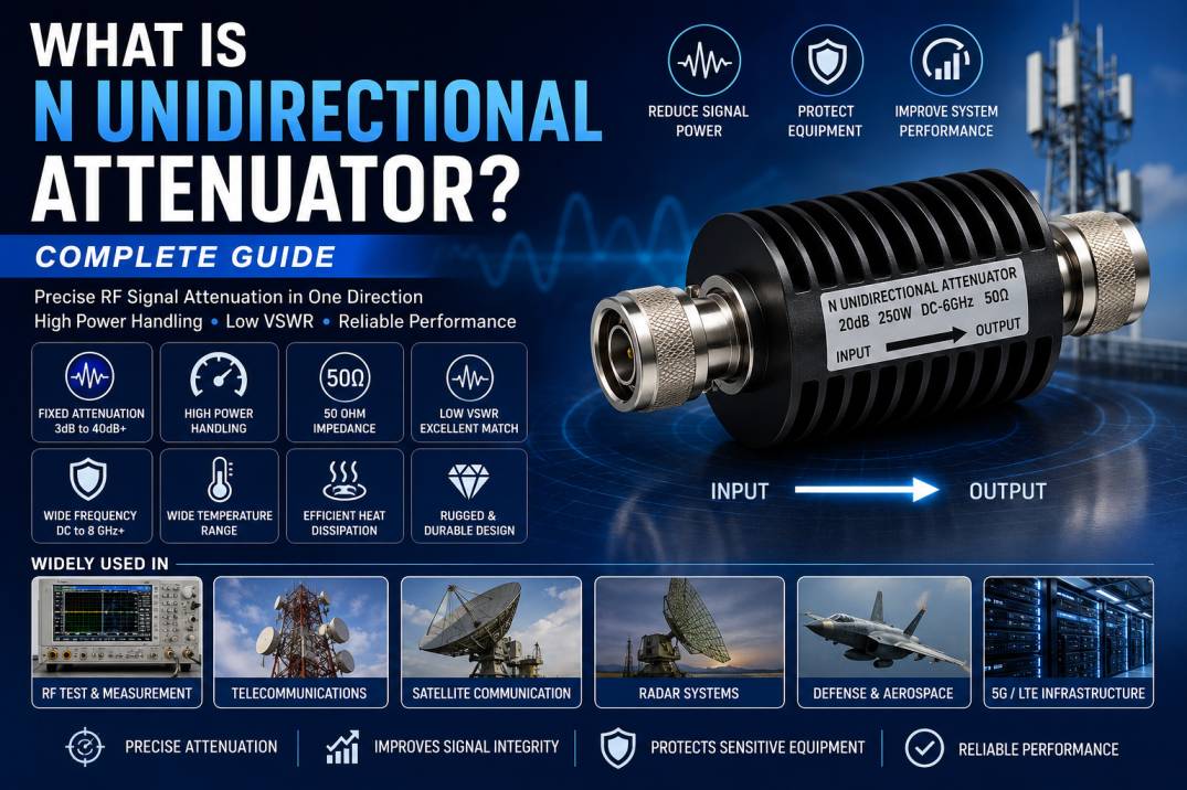
An N Unidirectional Attenuator is a passive RF component used to reduce the power level of a radio-frequency signal by a specified amount while maintaining a controlled impedance and minimizing unwanted reflections. It uses Type N coaxial connectors and is specifically designed to operate with a defined input and output direction.
Unlike a conventional bidirectional attenuator, a unidirectional attenuator has a specified input port and output port. The component’s power-handling capability and RF performance are characterized for signal flow in that direction. High-power N-type unidirectional attenuators are commonly used in RF testing, wireless infrastructure, telecommunications, radar, satellite communications, and high-power RF systems.
How Does an N Unidirectional Attenuator Work?
An N unidirectional attenuator normally contains a precision resistive attenuation network housed inside a shielded RF enclosure. When an RF signal enters through the designated input port, the attenuator reduces the signal power by a fixed amount before delivering the lower-power signal to the output.
For example, a 20 dB attenuator reduces the output power to approximately 1/100 of the input power, while a 30 dB attenuator reduces it to approximately 1/1000.
The attenuation network also helps maintain the required characteristic impedance, commonly 50 Ohms, so that the RF system experiences minimal additional mismatch.
In high-power versions, the attenuator must also dissipate substantial RF energy as heat. Therefore, high-power designs may use large heat sinks, finned housings, forced-air cooling, or other thermal-management techniques. Some high-power N attenuators are rated for hundreds of watts and are explicitly specified for operation in only one direction.
Why Is It Called a Unidirectional Attenuator?
The term unidirectional refers primarily to the specified direction of operation and power handling.
The input and output ports are not necessarily interchangeable. Manufacturers may specify one connector as the input and the other as the output, particularly for high-power products. Connecting the output as the input can result in performance outside the rated specifications or, in some designs, damage to the attenuator.
For example, some N-type high-power attenuators specifically instruct users not to reverse the input and output connections.
Therefore, the arrows, labels, markings, or datasheet instructions should always be checked before installation.
What Is an N-Type Connector?
The N connector, commonly called a Type N connector, is a threaded coaxial RF connector designed for reliable microwave and RF applications.
It provides:
- Secure threaded coupling
- Good mechanical strength
- Reliable electrical contact
- Effective RF shielding
- Weather-resistant configurations
- 50 Ohm and 75 Ohm variants depending on design
N connectors are widely used in antennas, base stations, RF equipment, wireless networks, measurement systems, and other RF infrastructure.
An N unidirectional attenuator typically uses an N Male to N Female configuration, although other connector arrangements can be manufactured for specific applications.
Key Features of N Unidirectional Attenuators
N unidirectional attenuators can provide a combination of electrical, mechanical, and thermal performance features.
Fixed Attenuation
The attenuation value is predetermined and remains essentially constant within the specified operating range.
Common attenuation values include:
- 3 dB
- 6 dB
- 10 dB
- 20 dB
- 30 dB
- 40 dB
- Higher values for specialized applications
The available attenuation range depends on the product design and power rating.
50 Ohm Impedance
Most RF N-type attenuators designed for wireless and microwave applications use a 50 Ohm impedance.
Maintaining 50 Ohm impedance helps minimize impedance mismatch and signal reflections.
High Power Handling
One of the major advantages of specialized N unidirectional attenuators is high power capability.
Commercial high-power examples are available with ratings such as 100 W, 200 W, 250 W, and higher depending on frequency, attenuation value, cooling conditions, and design.
Wide Frequency Operation
N unidirectional attenuators are available for different frequency ranges.
Depending on the design, products may operate from DC through several GHz. For example, high-power commercial N attenuators are available for ranges extending to 8 GHz and beyond.
Low VSWR
A well-designed attenuator provides a good impedance match at its ports.
Low VSWR helps reduce reflections and improves overall RF system performance.
Attenuation Accuracy
Precision attenuators are designed to maintain the specified attenuation value across the operating frequency range.
High-quality models may also specify attenuation flatness, which describes how consistently the attenuation is maintained as frequency changes.
Technical Specifications of N Unidirectional Attenuators
Typical specifications can include:
| Parameter | Typical Specification |
|---|---|
| Component Type | Fixed RF Attenuator |
| Connector Type | N-Type |
| Connector Configuration | N Male to N Female |
| Impedance | 50 Ohm |
| Attenuation | 3 dB to 40 dB or higher |
| Frequency | DC to several GHz |
| Power Rating | Application dependent |
| VSWR | Low VSWR design |
| Construction | Coaxial resistive network |
| Housing | Aluminum or other RF-grade metal |
| Operating Temperature | Application dependent |
| Direction | Defined Input to Output |
| Application | RF, Telecom, Test, Radar, Satellite |
Actual specifications vary significantly between models. The manufacturer’s datasheet should always be used for the final frequency, power, VSWR, temperature, and attenuation specifications.
N Unidirectional Attenuator vs Bidirectional Attenuator
The primary difference is how the component is specified for signal direction and power handling.
N Unidirectional Attenuator
- Has defined input and output
- Designed for operation in a specified direction
- Often used for high-power applications
- May have asymmetric power-handling specifications
- Requires correct orientation during installation
Bidirectional Attenuator
- Can generally be used in either direction
- Designed to provide comparable attenuation characteristics in both directions
- Commonly used in general RF test and signal-conditioning applications
For high-power applications, the direction marking should never be ignored.
How Much Does an N Unidirectional Attenuator Reduce Signal Power?
Attenuation is measured in decibels (dB).
Some common examples are:
- 3 dB: approximately half the power
- 6 dB: approximately one-quarter of the power
- 10 dB: approximately one-tenth of the power
- 20 dB: approximately one-hundredth of the power
- 30 dB: approximately one-thousandth of the power
- 40 dB: approximately one-ten-thousandth of the power
For example, if a 100 W RF signal passes through an ideal 20 dB attenuator, the theoretical output power is approximately 1 W, with the remaining power dissipated within the attenuator.
Applications of N Unidirectional Attenuators
RF Test and Measurement
N unidirectional attenuators are used to reduce high-level RF signals before they reach sensitive measurement equipment.
Applications include:
- Spectrum analyzers
- Signal generators
- RF power meters
- Network analyzers
- RF test benches
- Transmitter testing
High-power attenuators are particularly useful when the RF source produces more power than the measurement instrument can safely accept.
Telecommunications
N attenuators are used in wireless infrastructure for controlled signal-level reduction.
Applications include:
- Cellular base stations
- LTE infrastructure
- 5G infrastructure
- RF distribution systems
- Wireless communication equipment
- Antenna systems
High-power N attenuators are specifically used in applications such as LTE and 5G MIMO infrastructure.
Satellite Communication
Satellite RF systems require accurate control of signal levels.
N attenuators can be used in:
- Ground stations
- RF test systems
- Satellite communication equipment
- Transmitter chains
- Receiver test setups
Radar Systems
Radar systems often operate with substantial RF power. High-power attenuators can be used during testing and signal conditioning to reduce transmitter output to levels appropriate for downstream equipment.
N-type high-power attenuators are also used in radar, electronic warfare, and related defense applications.
Defense and Aerospace
Defense and aerospace RF systems require reliable components capable of handling demanding electrical and environmental conditions.
N unidirectional attenuators can be used in:
- RF transmitters
- Radar test systems
- Electronic warfare systems
- RF power measurement
- Communication equipment
- Laboratory test systems
RF Power Measurement
When measuring high-power RF signals, directly connecting a transmitter to sensitive measurement equipment can cause overload or damage.
An N unidirectional attenuator can reduce the signal to a safer measurement level while maintaining a controlled impedance.
Benefits of N Unidirectional Attenuators
Protects RF Equipment
Attenuation reduces the power delivered to sensitive RF components and instruments.
Controls Signal Levels
It allows engineers to establish a desired RF power level within a transmission or measurement chain.
Improves Measurement Safety
High-power signals can be reduced before reaching test instruments.
Maintains Impedance Matching
A properly designed 50 Ohm attenuator minimizes additional mismatch.
Handles High RF Power
Specialized designs can dissipate significant RF power through engineered thermal-management systems.
Provides Repeatable Attenuation
Fixed attenuation values offer predictable and repeatable signal reduction.
Reduces Reflections
Good impedance matching helps maintain low VSWR and minimizes unwanted reflected energy.
N Unidirectional Attenuator Construction
A typical high-power N unidirectional attenuator may contain several important elements.
Precision Resistive Network
The internal resistors establish the desired attenuation value.
RF Shielding
A conductive housing helps prevent unwanted electromagnetic leakage and interference.
N-Type Connectors
The connectors provide mechanical attachment and RF transmission between the attenuator and coaxial system.
Heat Dissipation Structure
High-power attenuators often use metal housings or finned heat sinks to transfer heat away from the internal resistive elements.
High-Temperature Materials
Specialized materials are selected to withstand the thermal stress generated during high-power operation.
Thermal Management in High-Power N Attenuators
Thermal management is one of the most important aspects of high-power attenuation.
RF power that is not delivered to the output must be dissipated as heat. As attenuation increases, a significant amount of input power may be converted into heat inside the attenuator.
For this reason, high-power models may incorporate:
- Large aluminum housings
- Finned heat sinks
- Forced-air cooling
- High-temperature resistors
- Thermal monitoring
- Derating specifications
Some 600 W N-type attenuators, for example, are designed with forced-air cooling and require continuous cooling during operation.
How to Select the Right N Unidirectional Attenuator
Choosing the correct attenuator requires evaluating several specifications.
Check the Attenuation Value
Determine how much signal reduction is required.
Check Input Power
The attenuator must safely handle the maximum continuous and peak RF power.
Verify Frequency Range
Choose a model whose specified frequency range covers the entire operating band.
Verify Impedance
For most RF wireless applications, verify that the attenuator is rated for 50 Ohms.
Check VSWR
Lower VSWR generally indicates better impedance matching.
Check Connector Configuration
Verify whether you require:
- N Male to N Female
- N Female to N Female
- N Male to N Male
- Other custom configurations
Confirm Direction
Make sure the transmitter or RF source is connected to the designated input port.
Evaluate Cooling Requirements
High-power applications may require heat sinks or forced-air cooling.
Common Mistakes When Using N Unidirectional Attenuators
Several installation errors can reduce performance or damage the component.
Reversing Input and Output
Do not reverse the attenuator unless the manufacturer explicitly states that reverse operation is permitted.
Exceeding Power Rating
Never operate continuously above the specified average power rating.
Ignoring Peak Power
Pulse and peak power can differ substantially from continuous-wave power.
Ignoring Frequency
An attenuator rated for a particular frequency range should not automatically be assumed to perform correctly at higher frequencies.
Poor Connector Installation
Incorrectly installed or damaged N connectors can increase VSWR and cause RF losses.
Inadequate Cooling
High-power attenuators require appropriate thermal management.
N Unidirectional Attenuator for 5G and Wireless Networks
Modern wireless infrastructure increasingly requires precise RF power management.
N unidirectional attenuators can be incorporated into:
- 4G LTE systems
- 5G networks
- MIMO infrastructure
- RF distribution networks
- Base-station testing
- Antenna testing
- Wireless laboratory setups
High-power N attenuators are commercially available for LTE and 5G MIMO infrastructure applications.
N Unidirectional Attenuator for RF Testing
RF testing requires accurate control of signal levels.
An N attenuator can be positioned between a high-power RF source and measurement equipment to reduce the signal to a suitable level.
This can help:
- Prevent instrument overload
- Protect sensitive inputs
- Establish controlled test conditions
- Improve repeatability
- Simplify transmitter testing
Maintenance and Handling
Proper handling helps maintain RF performance.
- Keep connectors clean
- Avoid mechanical impact
- Do not exceed rated power
- Follow the input/output direction
- Maintain adequate ventilation
- Use the recommended cooling system
- Protect connectors when not in use
- Inspect connectors before installation
- Follow the manufacturer’s derating requirements
Difference Between N Attenuator and N Termination
An N attenuator reduces the signal level while allowing the remaining RF signal to continue through the output port.
An N termination is primarily designed to absorb RF power at the end of a transmission line.
Therefore:
N Attenuator: Signal enters → signal is reduced → attenuated signal exits
N Termination: Signal enters → RF energy is absorbed → no signal output
Both components are important RF accessories, but they perform different functions.
Why Choose Precision N Unidirectional Attenuators?
A precision N unidirectional attenuator provides controlled RF attenuation with reliable mechanical and electrical performance.
Important characteristics include:
- Accurate attenuation
- Stable impedance
- Low VSWR
- Good attenuation flatness
- High power capability
- Reliable N-type connectivity
- Rugged construction
- Thermal stability
- Wide frequency operation
High-power commercial models demonstrate how N attenuators can combine significant power handling with wideband operation and controlled VSWR.
Conclusion
An N Unidirectional Attenuator is a precision passive RF component designed to reduce signal power by a specified amount while maintaining controlled impedance and reliable RF performance in a defined direction. Its N-type coaxial interface makes it suitable for a wide range of RF and microwave applications, while high-power versions are engineered to safely dissipate substantial RF energy.
These attenuators are particularly valuable in RF test and measurement, telecommunications, 4G and 5G infrastructure, satellite communication, radar, aerospace, defense, and high-power transmitter systems. Selecting the correct attenuation value, frequency range, impedance, power rating, VSWR, connector configuration, and operating direction is essential for safe and reliable operation.
Frequently Asked Questions About N Unidirectional Attenuators
1. What is an N Unidirectional Attenuator?
An N unidirectional attenuator is a passive RF device with N-type connectors that reduces RF signal power by a fixed amount and is designed to operate in a specified direction.
2. What is the main purpose of an N attenuator?
Its primary purpose is to reduce RF signal power to a controlled level while maintaining impedance matching and minimizing signal reflections.
3. Why is an N attenuator called unidirectional?
It is called unidirectional because the manufacturer specifies a particular input and output direction, especially for power handling and RF performance.
4. Can an N unidirectional attenuator be used in reverse?
Not necessarily. Some unidirectional attenuators must not be operated in reverse. Always follow the manufacturer’s input/output markings and datasheet.
5. What impedance is commonly used with N RF attenuators?
Most N-type RF attenuators used in wireless and microwave systems are designed for 50 Ohm impedance.
6. What attenuation values are available?
Common values include 3 dB, 6 dB, 10 dB, 20 dB, 30 dB, and 40 dB, with higher values available for specialized applications.
7. Can N unidirectional attenuators handle high RF power?
Yes. Specialized high-power N attenuators are available with power ratings ranging from tens of watts to hundreds of watts and beyond, depending on frequency, attenuation, cooling, and design.
8. Where are N unidirectional attenuators used?
They are used in RF testing, telecommunications, 4G and 5G infrastructure, satellite communications, radar, defense, aerospace, and high-power RF systems.
9. What is the difference between an N attenuator and an N termination?
An N attenuator reduces a signal and passes the remaining signal to its output. An N termination absorbs RF power at the end of a transmission line.
10. How do I choose an N unidirectional attenuator?
Consider attenuation, frequency range, impedance, maximum continuous and peak power, VSWR, connector configuration, cooling requirements, temperature range, and specified signal direction.










