
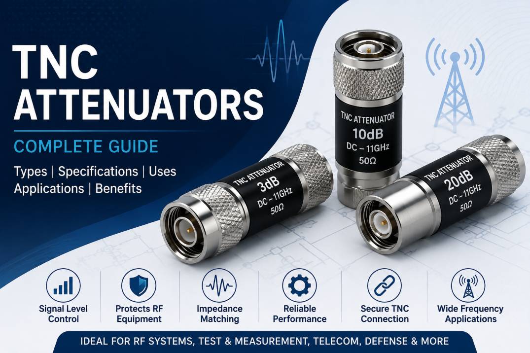
TNC attenuators are passive RF components designed to reduce the power level of radio frequency signals by a specific amount while maintaining a controlled impedance and minimizing signal reflections. The term TNC refers to the threaded Neill–Concelman connector interface, which provides a secure and mechanically stable connection compared with bayonet-style interfaces such as BNC.
TNC attenuators are widely used in RF communication systems, wireless networks, antenna systems, test and measurement equipment, instrumentation, defense electronics, and other high-frequency applications where accurate signal-level control is required.
An RF attenuator does not amplify or reshape the signal. Instead, it introduces a controlled amount of loss, normally expressed in decibels (dB). For example, a 3 dB TNC attenuator reduces the available power by approximately one-half, while a 10 dB attenuator reduces the power to approximately one-tenth.
TNC attenuators are particularly useful when engineers need to protect sensitive equipment, prevent receiver overload, improve impedance matching, control signal levels, or create predictable test conditions.
What Is a TNC Connector?
TNC stands for Threaded Neill–Concelman. It is a threaded RF coaxial connector derived from the BNC connector design.
Unlike BNC connectors, which use a bayonet locking mechanism, TNC connectors use a threaded coupling mechanism. This provides a more secure connection and better resistance to vibration and mechanical movement.
TNC connectors are commonly available in 50-ohm configurations for RF and microwave applications. They can be used across a broad range of frequencies depending on the connector design, materials, cable construction, and manufacturing tolerances.
A TNC attenuator combines this connector interface with an internal resistive attenuation network that provides a specified amount of RF signal loss.
What Is a TNC Attenuator?
A TNC attenuator is an RF passive device equipped with a TNC connector interface and designed to reduce the amplitude or power of an RF signal by a defined amount.
Typical attenuation values include:
- 1 dB
- 2 dB
- 3 dB
- 5 dB
- 6 dB
- 10 dB
- 15 dB
- 20 dB
- 30 dB
The appropriate attenuation value depends on the required RF power level, system gain, receiver sensitivity, transmitter output, and test configuration.
TNC attenuators are generally designed around a 50-ohm characteristic impedance for RF communication and instrumentation applications.
How Does a TNC Attenuator Work?
A TNC attenuator works by introducing a controlled amount of electrical resistance into the RF signal path.
The internal attenuation network is designed to maintain the desired impedance while dissipating a portion of the RF signal energy as heat.
For a matched RF system, attenuation in decibels is related to power ratio by:
Attenuation (dB) = 10 log10(Pin / Pout)
Where:
Pin is the input power and Pout is the output power.
For example, a 10 dB attenuator provides an output power that is one-tenth of the input power under a matched condition.
The attenuator therefore allows engineers to control signal levels without requiring active electronics.
Why Are TNC Attenuators Used in RF Systems?
TNC attenuators provide several important functions in RF systems.
Signal Level Control
They allow engineers to reduce excessive RF signal power to an appropriate operating level.
Receiver Protection
A strong RF signal can overload or damage sensitive receiver inputs. A properly selected attenuator can reduce the signal before it reaches the receiver.
Impedance Matching
Precision attenuators can help improve the effective impedance environment between connected RF components and reduce the impact of impedance mismatch.
Test and Measurement
Attenuators are frequently used between signal generators, VNAs, spectrum analyzers, receivers, amplifiers, and other RF test equipment.
Gain Adjustment
Engineers can use fixed attenuation to control the overall gain of an RF signal chain.
Isolation
An attenuator can provide additional isolation between two RF circuits, reducing the effect of reflections and interactions between connected components.
Main Types of TNC Attenuators
TNC attenuators can be categorized according to attenuation value, connector gender, construction, power rating, and application.
Fixed TNC Attenuators
Fixed TNC attenuators provide a predetermined attenuation value.
Common options include 3 dB, 6 dB, 10 dB, 20 dB, and 30 dB.
They are preferred when a stable and repeatable amount of attenuation is required.
TNC Male to TNC Female Attenuators
This configuration is commonly used as an inline attenuator. One end connects to a TNC female port and the other end connects to a TNC male port.
TNC Female to TNC Female Attenuators
These attenuators are useful when two male TNC interfaces need to be connected while maintaining a specified amount of signal attenuation.
TNC Male to TNC Male Attenuators
These configurations can be used when two female TNC interfaces are present in the RF system.
High-Power TNC Attenuators
High-power TNC attenuators are designed to dissipate greater amounts of RF energy. They require appropriate thermal design and power handling capabilities.
Precision TNC Attenuators
Precision models are manufactured with tighter electrical tolerances and are intended for laboratory, calibration, measurement, and instrumentation applications.
Important Specifications of TNC Attenuators
When selecting a TNC attenuator, several specifications should be evaluated.
Attenuation
Attenuation is the amount of signal reduction provided by the device and is normally specified in dB.
Frequency Range
The operating frequency range indicates the frequencies over which the attenuator is designed to maintain its specified electrical performance.
Impedance
Most RF TNC attenuators used in communication and instrumentation applications are designed for 50-ohm systems.
VSWR
Voltage Standing Wave Ratio indicates how well the attenuator maintains impedance matching.
Lower VSWR generally indicates better impedance matching and reduced reflections.
Return Loss
Return loss describes the amount of reflected RF power caused by impedance mismatch. Higher return loss generally indicates better matching.
Power Rating
Power rating indicates how much RF power the attenuator can safely dissipate under specified conditions.
Power handling may be specified as continuous-wave power, average power, peak power, or pulse power depending on the product.
Connector Gender
TNC attenuators can be supplied with different male and female connector configurations. Connector gender should match the interfaces in the RF system.
Insertion Loss
For an attenuator, the specified attenuation is the intended signal loss. Additional insertion-loss characteristics and frequency-dependent variation may also be important in precision applications.
Operating Temperature
For outdoor, aerospace, defense, industrial, or high-power applications, the operating temperature range should be considered carefully.
TNC Attenuator Frequency Range
The usable frequency range of a TNC attenuator depends on the connector design and internal RF construction.
Standard TNC components are commonly used in RF systems ranging from lower RF frequencies into the microwave region, while specialized precision designs can support higher frequencies.
The actual operating frequency should always be verified from the manufacturer’s datasheet rather than assumed solely from the connector type.
TNC Attenuator Power Handling
Power handling is one of the most important specifications when selecting an RF attenuator.
A TNC attenuator absorbs part of the input RF power and converts it into heat. If the input power exceeds the device’s rated capacity, excessive temperature can cause performance degradation or permanent damage.
For example, if a 10 W RF signal is applied to a 3 dB attenuator, approximately half of the available power is dissipated within the attenuator under an ideal matched condition.
Therefore, engineers should consider:
- Input RF power
- Attenuation value
- Continuous or pulsed operation
- Ambient temperature
- Duty cycle
- Cooling conditions
- Frequency
- Maximum allowable temperature
TNC Attenuators and Impedance Matching
Maintaining a consistent impedance is essential in RF systems.
A mismatch between a transmitter, cable, attenuator, antenna, or receiver can generate reflected power. These reflections can increase VSWR and reduce overall system performance.
A properly designed 50-ohm TNC attenuator helps maintain a controlled RF environment while reducing the signal level.
This makes attenuators useful in systems where signal integrity and predictable RF behavior are important.
TNC Attenuator Applications
TNC attenuators are used across numerous industries and RF applications.
Wireless Communication
They can be used in wireless communication equipment to control signal levels and protect receiver inputs.
RF Test and Measurement
TNC attenuators are commonly used with RF test setups involving signal generators, spectrum analyzers, network analyzers, and RF power meters.
Antenna Systems
They can be installed in antenna signal paths when signal levels need to be reduced or controlled.
Telecom Equipment
TNC attenuators can be used in telecommunications and wireless infrastructure where controlled RF power is required.
Defense and Aerospace
RF attenuation is important in radar, communication, electronic test equipment, and other defense-related systems.
Laboratory Equipment
Precision TNC attenuators are useful for laboratory measurements and controlled RF experiments.
Broadcast Systems
Attenuators can be used to control RF levels between transmitters, monitoring equipment, and associated signal-processing equipment.
RF Development and Prototyping
Engineers can use TNC attenuators during prototype testing to simulate cable loss or create controlled signal conditions.
Advantages of TNC Attenuators
TNC attenuators offer several benefits in RF applications.
- Threaded and secure RF connection
- Controlled signal attenuation
- 50-ohm impedance options
- Reliable mechanical connection
- Improved vibration resistance compared with bayonet-style connections
- Available in multiple attenuation values
- Suitable for test and measurement applications
- Available in various connector gender configurations
- Useful for receiver protection
- Supports controlled RF power levels
- Compact inline installation
- Suitable for many communication and RF systems
TNC vs BNC Attenuators
TNC and BNC attenuators can perform similar electrical functions, but their connector interfaces differ.
TNC connectors use threaded coupling, while BNC connectors use a bayonet locking mechanism.
TNC is often preferred where mechanical security and vibration resistance are important. BNC is widely used where quick connection and disconnection are desirable.
The choice depends on the equipment interface, frequency requirements, environmental conditions, and mechanical requirements.
TNC vs SMA Attenuators
TNC and SMA attenuators are both used in RF systems, but they serve somewhat different application needs.
SMA connectors are compact and widely used in microwave and high-frequency applications. TNC connectors provide a threaded connection with a larger physical form factor and are commonly used in communication and rugged RF systems.
Selection should be based on frequency, size, power handling, connector compatibility, environmental requirements, and system design.
How to Select the Right TNC Attenuator
Choosing the correct TNC attenuator requires evaluation of the complete RF system.
Determine the Required Attenuation
Calculate how much signal reduction is needed. Common values include 3 dB, 6 dB, 10 dB, and 20 dB.
Check Frequency
Ensure that the attenuator’s specified frequency range covers the complete operating band.
Verify Impedance
For most RF communication applications, select a 50-ohm TNC attenuator when the rest of the RF system is 50 ohms.
Check Power Rating
Select a power rating with sufficient margin above the actual operating power.
Select Connector Gender
Confirm whether the equipment requires TNC male, TNC female, or another connector configuration.
Evaluate VSWR and Return Loss
For precision RF applications, choose an attenuator with suitable VSWR and return-loss specifications.
Consider Environmental Conditions
Outdoor and industrial installations may require resistance to temperature variation, vibration, moisture, corrosion, and other environmental stresses.
Common Mistakes When Using TNC Attenuators
Incorrect attenuator selection can negatively affect RF system performance.
Common mistakes include:
- Selecting an attenuator with insufficient power handling
- Using the wrong impedance
- Operating outside the specified frequency range
- Ignoring connector gender
- Using damaged connectors
- Applying excessive mechanical torque
- Ignoring temperature limitations
- Failing to account for cumulative attenuation
- Using a low-quality attenuator in precision measurement applications
- Assuming connector type alone determines frequency capability
TNC Attenuators in RF Testing
TNC attenuators are particularly useful in controlled RF test environments.
For example, an engineer testing a receiver can insert a known-value attenuator between a signal generator and the receiver input. This allows the engineer to reduce the signal to a controlled level and evaluate receiver sensitivity.
Attenuators can also be used to protect expensive test equipment from excessive RF power.
In network-analysis applications, precision attenuators may help create repeatable test configurations and manage signal levels between RF instruments and devices under test.
TNC Attenuators for 5G and Wireless Applications
Modern wireless systems require accurate RF signal management across multiple frequency bands.
TNC attenuators can be useful in supporting equipment, test setups, antenna systems, and RF infrastructure where a threaded RF interface is required.
Their usefulness depends on the exact frequency band, power level, connector specification, and environmental requirements of the application.
For higher-frequency 5G and advanced microwave testing, engineers should select TNC attenuators based on verified datasheet performance rather than relying only on the connector name.
TNC Attenuators for Defense and Aerospace
Defense and aerospace RF systems often require reliable components that can maintain stable performance under demanding operating conditions.
TNC attenuators may be used in RF communication, radar-related equipment, test systems, electronic instrumentation, and signal-conditioning applications.
For these applications, engineers may need to evaluate:
- High mechanical reliability
- Temperature stability
- Low VSWR
- High return loss
- Power handling
- Environmental sealing
- Vibration resistance
- Connector durability
- Traceability and quality control
Manufacturing of TNC Attenuators
High-quality TNC attenuators require precision mechanical and electrical manufacturing.
The connector body and mating components must be manufactured with accurate dimensions to maintain reliable mechanical and RF performance.
The internal attenuation network must also be designed to provide the required impedance, attenuation accuracy, power handling, and frequency response.
Typical manufacturing considerations include:
- Precision machining
- High-quality dielectric materials
- Controlled impedance design
- Precision resistive elements
- Surface finishing
- Connector dimensional inspection
- Electrical testing
- VSWR testing
- Return-loss testing
- Attenuation verification
- Power-handling verification where applicable
Testing of TNC Attenuators
RF attenuators can be tested using specialized RF measurement equipment.
Important tests may include:
Attenuation Accuracy
Measures whether the actual attenuation corresponds to the specified dB value.
VSWR Testing
Determines the impedance-matching performance.
Return Loss Testing
Measures reflected signal performance.
Frequency Response
Checks whether attenuation remains within specification across the operating frequency range.
Power Testing
For high-power models, power-handling performance can be evaluated under controlled conditions.
Mechanical Inspection
Connector dimensions, coupling mechanisms, plating, and overall construction can be inspected to ensure reliable mating.
TNC Attenuator Maintenance
TNC attenuators generally require minimal maintenance, but proper handling can significantly extend their service life.
Keep connector interfaces clean and free from dust or contamination. Inspect mating surfaces before connection and avoid forcing incompatible connectors together.
When installing a TNC attenuator, use appropriate RF connector practices and avoid excessive tightening.
For precision laboratory applications, periodic electrical verification may be appropriate depending on usage frequency and measurement requirements.
Frequently Asked Questions About TNC Attenuators
What is a TNC attenuator?
A TNC attenuator is a passive RF component that reduces the power level of an RF signal by a specified amount while providing a TNC threaded connector interface.
What does TNC stand for?
TNC stands for Threaded Neill–Concelman, referring to the threaded version of the Neill–Concelman RF connector family.
Are TNC attenuators 50 ohms?
Many RF TNC attenuators are designed for 50-ohm systems. However, the exact impedance should always be verified from the product specification.
What attenuation values are available?
Common attenuation values include 3 dB, 6 dB, 10 dB, 20 dB, and 30 dB, although other values can also be manufactured.
What is a TNC attenuator used for?
TNC attenuators are used for RF signal-level control, receiver protection, impedance management, RF testing, antenna systems, telecommunications, and instrumentation.
Are TNC attenuators suitable for high-frequency applications?
They can be suitable for high-frequency applications when the specific attenuator is designed and rated for the required frequency range.
How do I choose a TNC attenuator?
Consider attenuation value, frequency range, impedance, power rating, connector gender, VSWR, return loss, environmental conditions, and application requirements.
What is the difference between a TNC and BNC attenuator?
The primary difference is the connector interface. TNC uses a threaded coupling mechanism, while BNC uses a bayonet coupling mechanism.
Can TNC attenuators be used for receiver protection?
Yes. A properly rated TNC attenuator can reduce excessive RF power before it reaches a sensitive receiver input.
Are TNC attenuators passive components?
Yes. TNC attenuators are passive RF components and do not require an external power supply.
Can TNC attenuators be customized?
Depending on the manufacturer, custom attenuation values, connector configurations, frequency ranges, power ratings, and mechanical designs may be available.
Conclusion
TNC attenuators are important passive RF components for controlling signal levels while maintaining a secure threaded RF connection. Their applications range from telecommunications and wireless systems to RF testing, antenna systems, aerospace, defense, and laboratory instrumentation.
When selecting a TNC attenuator, engineers should consider attenuation value, frequency range, impedance, power handling, VSWR, return loss, connector configuration, and environmental requirements. Selecting a component according to these parameters helps ensure reliable RF performance and protects sensitive equipment from excessive signal levels.
For RF system designers, test engineers, telecom professionals, and equipment manufacturers, TNC attenuators provide a practical solution for controlled signal attenuation and dependable RF connectivity










