
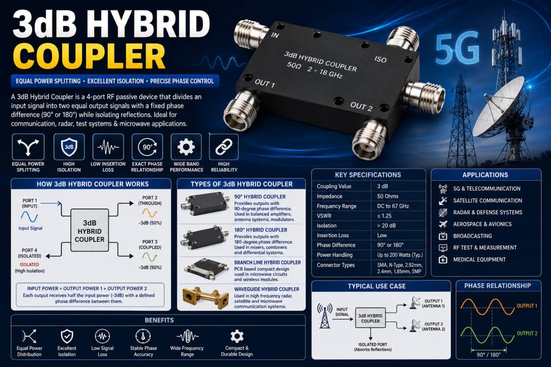
A 3dB Hybrid Coupler is one of the most important passive components used in radio frequency (RF), microwave, and communication systems. It is specifically designed to divide an input signal equally into two output signals while maintaining a precise phase relationship between the outputs. Unlike ordinary power splitters, a 3dB Hybrid Coupler provides both equal power distribution and isolation between output ports, making it an essential device in high-frequency applications where signal integrity and phase accuracy are critical.
Modern RF systems such as 4G and 5G networks, satellite communication, radar systems, broadcasting equipment, defense electronics, wireless infrastructure, laboratory test systems, and microwave communication all rely on hybrid couplers to improve performance and reduce signal interference. By maintaining equal power division and minimizing reflections, these couplers contribute significantly to stable system operation and higher communication efficiency.
A 3dB Hybrid Coupler is available in various frequency ranges, connector types, power ratings, and mechanical configurations to meet different industrial and commercial requirements. Their ability to support bidirectional signal transmission and provide excellent isolation makes them indispensable in modern RF engineering.
This comprehensive guide explains everything you need to know about 3dB Hybrid Couplers, including their working principle, construction, specifications, types, applications, advantages, and selection criteria.
What Is a 3dB Hybrid Coupler?
A 3dB Hybrid Coupler is a four-port passive RF device that divides an input signal equally into two output ports, with each output receiving half of the input power. Since half the power corresponds to a 3 dB reduction, the device is called a 3dB Hybrid Coupler.
In addition to equal power splitting, the coupler introduces a specific phase difference between the output signals, commonly 90 degrees or 180 degrees, depending on the coupler design. The fourth port is isolated, preventing unwanted signal reflections from affecting the input.
Because of this unique functionality, 3dB Hybrid Couplers are widely used in RF signal combining, power distribution, antenna feeding, balanced amplifiers, and microwave measurement systems.
How Does a 3dB Hybrid Coupler Work?
A 3dB Hybrid Coupler consists of four ports:
- Input Port
- Through Port
- Coupled Port
- Isolated Port
When an RF signal enters the input port, the coupler divides the signal equally between the through port and the coupled port. Each output receives approximately 50% of the input power, resulting in a 3 dB reduction.
Depending on the design, the two output signals maintain a fixed phase relationship, usually 90° or 180°. Any reflected signals from the output ports are directed toward the isolated port instead of returning to the source, helping protect sensitive RF equipment and improving overall system performance.
Construction of a 3dB Hybrid Coupler
A 3dB Hybrid Coupler is manufactured using precision microwave engineering techniques to ensure accurate signal division and excellent electrical performance.
Input and Output Ports
The coupler features four precision RF ports designed for signal input, output, coupling, and isolation.
Internal Transmission Lines
Specially designed transmission lines distribute RF energy while maintaining impedance and phase accuracy.
Dielectric Substrate
High-frequency dielectric materials provide electrical insulation and stable microwave performance.
Common materials include:
- PTFE
- Ceramic
- Rogers Laminates
- Alumina
Metallic Housing
The housing provides mechanical protection and excellent electromagnetic shielding.
Common materials include:
- Aluminum
- Brass
- Stainless Steel
Types of 3dB Hybrid Couplers
Several types of hybrid couplers are available for different RF applications.
90 Degree Hybrid Coupler
Provides two equal output signals with a 90-degree phase difference.
Applications include:
- Balanced amplifiers
- Quadrature modulators
- Antenna arrays
180 Degree Hybrid Coupler
Produces two equal signals that are 180 degrees out of phase.
Applications include:
- Mixers
- RF combiners
- Differential communication systems
Branch Line Hybrid Coupler
A compact PCB-based coupler commonly used in microwave circuits.
Waveguide Hybrid Coupler
Designed for extremely high-frequency microwave and radar systems.
Stripline Hybrid Coupler
Used in integrated microwave circuits requiring excellent phase accuracy.
Technical Specifications
| Specification | Typical Value |
| Frequency Range | DC to 67 GHz (depending on model) |
| Coupling Value | 3 dB |
| Impedance | 50 Ohms |
| VSWR | ≤ 1.25 |
| Insertion Loss | Low |
| Isolation | Greater than 20 dB |
| Return Loss | Greater than 20 dB |
| Phase Difference | 90° or 180° |
| Connector Types | SMA, N-Type, 2.92 mm, 2.4 mm |
| Operating Temperature | -55°C to +85°C |
Common Connector Types
3dB Hybrid Couplers are available with several connector interfaces.
Popular connector types include:
- SMA
- N-Type
- 2.92 mm
- 2.4 mm
- 1.85 mm
- TNC
- BNC
- SMP
- SMPM
Frequency Range
Modern 3dB Hybrid Couplers support a wide range of operating frequencies.
Typical frequency ranges include:
- DC to 1 GHz
- DC to 3 GHz
- DC to 6 GHz
- DC to 12 GHz
- DC to 18 GHz
- DC to 26.5 GHz
- DC to 40 GHz
- DC to 50 GHz
- DC to 67 GHz
Specialized microwave couplers are available for frequencies exceeding 100 GHz.
Applications of 3dB Hybrid Couplers
5G Communication
Power division in massive MIMO antenna systems
Beamforming networks
Small-cell infrastructure
Wireless Communication
Base stations
Repeaters
Distributed antenna systems
Satellite Communication
Ground stations
Satellite transceivers
VSAT terminals
Radar Systems
Military radar
Weather radar
Air traffic control
Navigation radar
Aerospace and Defense
Electronic warfare
Communication systems
Missile guidance
Aircraft communication
RF Test and Measurement
Network analyzers
Spectrum analyzers
Signal generators
Calibration laboratories
Broadcasting
Radio transmission
Television broadcasting
Microwave links
Medical Equipment
MRI systems
RF imaging
Medical communication devices
Advantages of 3dB Hybrid Couplers
- Equal power division
- Excellent isolation
- Low insertion loss
- High return loss
- Stable phase relationship
- Wide frequency coverage
- High reliability
- Compact design
- Superior RF performance
- Excellent impedance matching
- Suitable for high-power applications
- Long operational life
Limitations of 3dB Hybrid Couplers
- Fixed coupling value
- Frequency-dependent performance
- Higher cost than basic power splitters
- Requires accurate impedance matching
- Performance varies outside rated frequency range
How to Choose the Right 3dB Hybrid Coupler
Before selecting a 3dB Hybrid Coupler, consider the following:
- Operating frequency
- Power handling capability
- Phase requirement (90° or 180°)
- Connector type
- Insertion loss
- Isolation
- Return loss
- VSWR
- Physical size
- Environmental conditions
3dB Hybrid Coupler vs Power Divider
| Feature | 3dB Hybrid Coupler | Power Divider |
| Number of Ports | Four | Two or Three |
| Power Split | Equal | Equal or Unequal |
| Phase Difference | Yes | No |
| Isolation | Excellent | Limited |
| Signal Combining | Yes | Limited |
| RF Performance | Superior | Standard |
| Reflection Handling | Excellent | Moderate |
Industries Using 3dB Hybrid Couplers
3dB Hybrid Couplers are extensively used in:
- Telecommunications
- 5G Networks
- Aerospace
- Defense
- Satellite Communication
- Broadcasting
- Medical Electronics
- RF Laboratories
- Industrial Automation
- Research and Development
Maintenance Tips
To ensure long-term reliability:
- Keep RF connectors clean.
- Avoid exceeding the rated power.
- Use proper torque when tightening connectors.
- Protect the device from moisture and dust.
- Verify connector integrity during maintenance.
- Store in a dry, temperature-controlled environment.
- Inspect periodically for mechanical damage.
Future Trends of 3dB Hybrid Couplers
The evolution of 5G, future 6G networks, satellite internet, autonomous vehicles, aerospace communication, and advanced radar technologies continues to drive innovation in 3dB Hybrid Coupler design. Manufacturers are developing compact couplers with wider bandwidths, lower insertion loss, improved isolation, enhanced power handling, and operation beyond 100 GHz. Integration with advanced RF modules and miniaturized microwave systems will further increase the demand for high-performance hybrid couplers in next-generation communication infrastructure.
Conclusion
A 3dB Hybrid Coupler is a critical passive RF component that enables equal power division, excellent port isolation, and precise phase control in microwave and communication systems. Its ability to maintain signal integrity while minimizing reflections makes it indispensable in 5G infrastructure, satellite communication, aerospace, defense, radar, medical electronics, broadcasting, and RF testing. Choosing the appropriate coupler based on frequency range, connector type, phase relationship, insertion loss, isolation, and power handling ensures reliable long-term performance in demanding RF applications.
Frequently Asked Questions (FAQs)
1. What is a 3dB Hybrid Coupler?
A 3dB Hybrid Coupler is a four-port passive RF device that splits an input signal equally into two output signals while maintaining a specific phase difference and providing excellent isolation.
2. How does a 3dB Hybrid Coupler work?
It divides the input RF signal equally between two output ports, with each output receiving half the input power, while the isolated port absorbs reflected signals.
3. What is the difference between a 90° and a 180° Hybrid Coupler?
A 90° Hybrid Coupler provides two outputs with a 90-degree phase difference, while a 180° Hybrid Coupler produces outputs that are 180 degrees out of phase.
4. Where are 3dB Hybrid Couplers used?
They are used in 5G networks, satellite communication, radar systems, RF test equipment, aerospace, defense, broadcasting, and medical electronics.
5. Why is it called a 3dB Hybrid Coupler?
It is called a 3dB Hybrid Coupler because each output receives half of the input power, corresponding to a power reduction of 3 dB.
6. What connector types are available?
Common connector options include SMA, N-Type, 2.92 mm, 2.4 mm, 1.85 mm, SMP, SMPM, TNC, and BNC.
7. What frequency range does a 3dB Hybrid Coupler support?
Depending on the model, operating frequencies range from DC up to 67 GHz, with specialized versions available for higher microwave frequencies.
8. What are the main advantages of a 3dB Hybrid Coupler?
Key benefits include equal power splitting, excellent isolation, low insertion loss, stable phase relationship, wide bandwidth, and high reliability.
9. How do I choose the right 3dB Hybrid Coupler?
Choose based on operating frequency, power rating, connector type, phase requirement, insertion loss, isolation, VSWR, and environmental conditions.
10. Can a 3dB Hybrid Coupler be used as a power combiner?
Yes. A 3dB Hybrid Coupler can function as both a power splitter and a power combiner, making it highly versatile in RF and microwave system designs.










