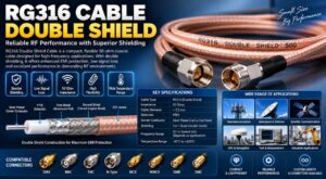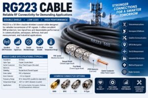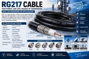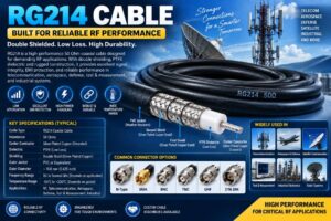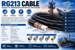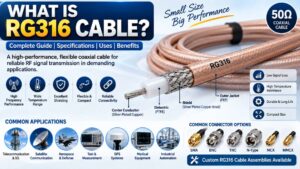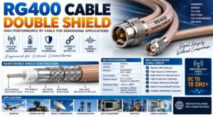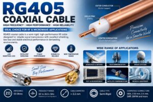
Choosing the right RF Coaxial Cable Assembly is essential for maintaining signal quality, reducing transmission losses, and ensuring reliable communication in RF and microwave systems. Whether you are working in telecommunications, aerospace, defense, satellite communication, broadcasting, or laboratory testing, selecting the proper cable assembly directly impacts overall system performance.
RF coaxial cable assemblies are designed to transfer high-frequency signals between components while minimizing attenuation, interference, and impedance mismatches. With numerous cable types, connector options, shielding configurations, and frequency ratings available, understanding the selection process helps engineers and buyers choose the most suitable solution.
This guide explains everything you need to know before selecting an RF coaxial cable assembly.
What is an RF Coaxial Cable Assembly?
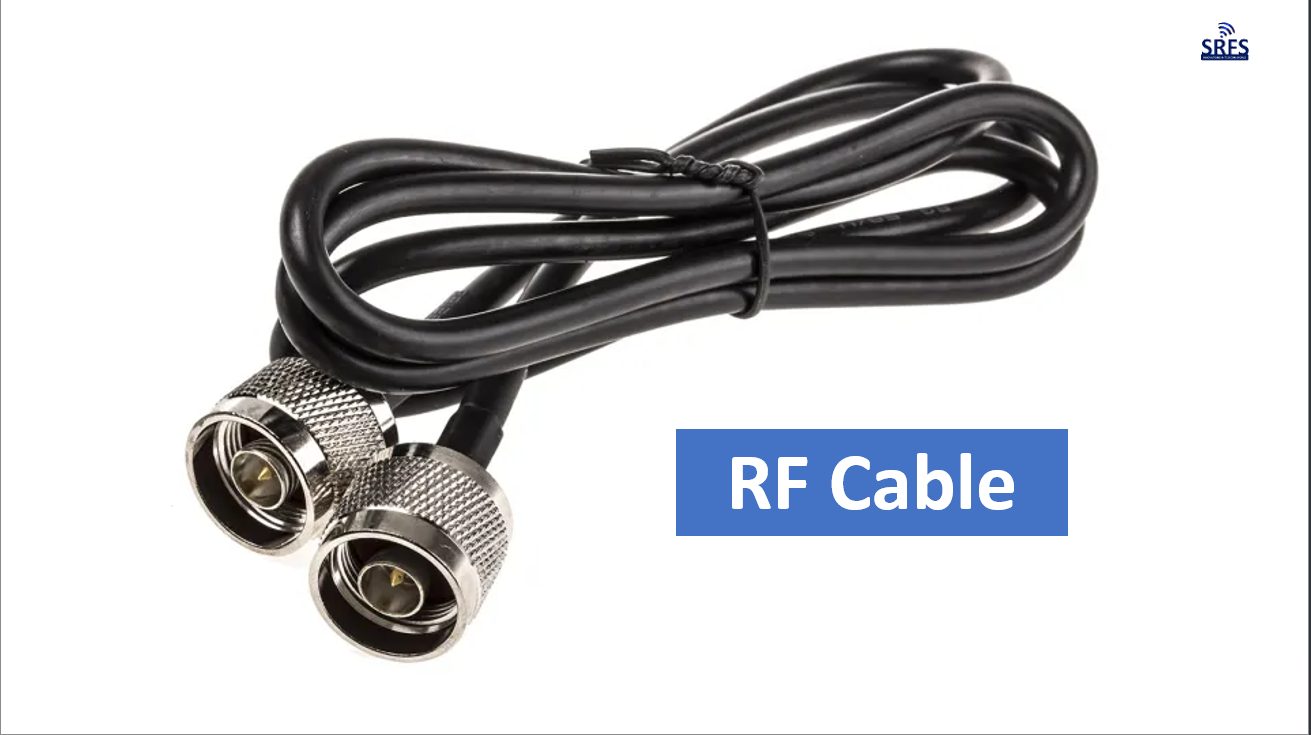
An RF Coaxial Cable Assembly is a complete cable system consisting of a coaxial cable fitted with RF connectors on both ends. It is designed to transmit radio frequency signals with minimal loss while maintaining a constant impedance, typically 50 Ohms or 75 Ohms.
A standard RF coaxial cable assembly consists of:
- Center conductor
- Dielectric insulation
- Outer conductor (shield)
- Protective outer jacket
- Precision RF connectors
The assembly is factory terminated and tested to ensure consistent electrical performance.
Why Proper Cable Selection Matters
Selecting the wrong RF cable assembly can lead to:
- Higher insertion loss
- Signal reflections
- Increased VSWR
- Poor impedance matching
- Reduced communication range
- Network downtime
- Equipment damage
- Lower system efficiency
The correct RF cable assembly ensures reliable operation throughout the system’s service life.
Factors to Consider When Selecting an RF Coaxial Cable Assembly
1. Operating Frequency
Frequency is the most important selection criterion.
Different cable assemblies support different frequency ranges.
Examples include:
- DC to 3 GHz
- DC to 6 GHz
- DC to 18 GHz
- DC to 26.5 GHz
- DC to 40 GHz
- DC to 50 GHz
- DC to 67 GHz
Higher frequencies require cables with lower attenuation and better shielding.
2. Cable Type
Different applications require different cable constructions.
Flexible Cable Assembly
Suitable for:
- General communication systems
- Laboratory equipment
- Mobile installations
- Indoor telecom applications
Advantages
- Easy installation
- Lower cost
- Excellent flexibility
Semi-Flexible Cable
Suitable for:
- Military electronics
- Satellite systems
- Microwave equipment
Advantages
- Lower insertion loss
- Better shielding
- Improved phase stability
Semi-Rigid Cable
Ideal for:
- Aerospace
- Radar
- High-frequency microwave systems
- Precision laboratory testing
Advantages
- Highest electrical performance
- Superior shielding
- Stable impedance
Low Loss Cable
Recommended for:
- Long cable runs
- Outdoor telecom towers
- Base stations
- 5G infrastructure
Advantages
- Lower attenuation
- Better signal strength
- Increased transmission distance
3. Impedance Selection
Most RF systems use either:
50 Ohm
Used in:
- Wireless communication
- RF testing
- Military systems
- Satellite communication
- Aerospace
- Cellular infrastructure
75 Ohm
Used in:
- Television broadcasting
- CCTV
- Video transmission
- Cable television
Always match cable impedance with the system impedance.
4. Frequency Loss (Insertion Loss)
Insertion loss determines how much signal power is lost while passing through the cable.
Lower insertion loss means:
- Better communication quality
- Longer transmission distance
- Improved signal strength
- Higher efficiency
For long-distance applications, choose low-loss RF cable assemblies.
5. VSWR Performance
Voltage Standing Wave Ratio (VSWR) measures impedance matching.
A lower VSWR indicates better performance.
Typical values:
- Excellent: Less than 1.20
- Very Good: 1.20–1.30
- Acceptable: 1.30–1.50
Lower VSWR reduces reflected power and improves efficiency.
6. Connector Type
Connector compatibility is essential.
Common RF connectors include:
- SMA
- N Type
- TNC
- BNC
- MMCX
- MCX
- SMP
- SMPM
- 2.92 mm
- 2.4 mm
- 1.85 mm
- UHF
- QMA
- FAKRA
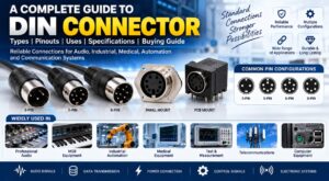
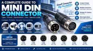
- Mini DIN
- 7/16 DIN
Select connectors compatible with your equipment and frequency range.
7. Cable Length
Cable length directly affects signal loss.
General recommendations:
- Use the shortest practical cable.
- Avoid unnecessary cable loops.
- Minimize connector transitions.
- Choose low-loss cable for long distances.
8. Shielding Effectiveness
Shielding protects signals from electromagnetic interference.
Better shielding provides:
- Reduced EMI
- Reduced RFI
- Cleaner signal transmission
- Higher system reliability
Double-shielded and triple-shielded cables are preferred for demanding environments.
9. Environmental Conditions
Consider installation conditions.
Important factors include:
- Temperature
- Moisture
- UV exposure
- Chemicals
- Dust
- Salt fog
- Vibration
- Mechanical stress
Outdoor applications require weather-resistant jackets.
Military systems require ruggedized cable assemblies.
10. Flexibility Requirements
If the cable moves frequently, choose flexible cable assemblies.
For fixed installations, semi-rigid cables provide better electrical performance.
11. Mechanical Durability
Industrial environments require durable cable assemblies capable of handling:
- Frequent bending
- Pulling forces
- Vibration
- Compression
- Abrasion
High-quality jackets improve cable lifespan.
12. Phase Stability
Applications such as radar, aerospace, and test equipment require excellent phase stability.
Temperature phase-stable cable assemblies maintain consistent electrical characteristics even under changing environmental conditions.
13. Power Handling Capacity
Higher RF power requires cable assemblies with:
- Larger conductors
- Better heat dissipation
- Higher-quality dielectric materials
Always verify the cable’s maximum power rating.
14. Indoor vs Outdoor Installation
Indoor Applications
- Flexible PVC jacket
- Lightweight construction
- Lower environmental protection requirements
Outdoor Applications
- UV-resistant jacket
- Waterproof construction
- Weather-resistant connectors
- Moisture sealing
Common RF Cable Assembly Applications
Telecommunications
RF coaxial cable assemblies connect:
- Cellular base stations
- DAS systems
- Small cells
- RF repeaters
- 4G infrastructure
- 5G infrastructure
Aerospace
Used in:
- Aircraft communication
- Navigation equipment
- Flight testing
- Avionics
- Satellite payloads
Defense
Military systems use RF cable assemblies in:
- Radar
- Electronic warfare
- Missile guidance
- Tactical communication
- Surveillance
Satellite Communication
Essential for:
- Ground stations
- Satellite terminals
- Earth stations
- VSAT systems
- Space communication
Medical Equipment
Applications include:
- MRI systems
- CT scanners
- Diagnostic imaging
- Medical RF equipment
Broadcasting
Used for:
- Television transmitters
- Radio stations
- Studio equipment
- Outside broadcasting vehicles
Industrial Automation
Supports:
- Wireless sensors
- Remote monitoring
- Factory automation
- Industrial communication systems
Advantages of Selecting the Right RF Coaxial Cable Assembly
Proper cable selection offers several benefits:
- Lower signal attenuation
- Better return loss
- Improved VSWR
- Longer cable life
- Reduced maintenance
- Better network reliability
- Higher transmission efficiency
- Enhanced system performance
- Lower operating costs
- Increased equipment protection
Common Mistakes to Avoid
Avoid these common errors when selecting an RF coaxial cable assembly:
- Choosing the wrong impedance
- Ignoring frequency ratings
- Using excessive cable lengths
- Selecting incompatible connectors
- Overlooking environmental conditions
- Ignoring insertion loss specifications
- Choosing low-quality cable materials
- Using incorrect shielding
- Ignoring power handling limits
- Purchasing untested cable assemblies
Why Choose a High-Quality RF Coaxial Cable Assembly?
Premium RF cable assemblies are manufactured with precision components to ensure:
- Consistent impedance
- Excellent return loss
- Low insertion loss
- Superior shielding
- High durability
- Reliable long-term performance
- Precision connector termination
- Stable high-frequency transmission
Factory-tested assemblies provide better reliability than field-terminated cables.
Conclusion
Selecting the appropriate RF Coaxial Cable Assembly is critical for achieving optimal RF system performance. The ideal cable assembly depends on operating frequency, impedance, connector type, cable construction, shielding, insertion loss, environmental conditions, and application requirements. Whether deploying a 5G network, designing a radar system, operating satellite communication equipment, or performing precision laboratory testing, choosing a high-quality RF cable assembly ensures maximum efficiency, signal integrity, and long-term reliability.
Investing in the right RF coaxial cable assembly reduces maintenance costs, improves network performance, and extends equipment life, making it an essential component in every modern RF communication system.
Frequently Asked Questions (FAQs)
1. What is an RF Coaxial Cable Assembly?
An RF Coaxial Cable Assembly is a coaxial cable with RF connectors attached at both ends, designed to transmit high-frequency signals with low loss and consistent impedance.
2. How do I choose the right RF Coaxial Cable Assembly?
Consider operating frequency, impedance, cable type, connector compatibility, insertion loss, shielding, cable length, environmental conditions, flexibility, and power handling requirements.
3. What is the difference between 50 Ohm and 75 Ohm RF cable assemblies?
A 50 Ohm cable assembly is used for RF communication, wireless networks, defense, aerospace, and test equipment, while a 75 Ohm cable assembly is mainly used for television broadcasting, CCTV, and video transmission.
4. Which connector types are commonly used with RF cable assemblies?
Common connector types include SMA, N Type, BNC, TNC, MMCX, MCX, SMP, SMPM, 2.92 mm, 2.4 mm, 1.85 mm, QMA, UHF, FAKRA, and Mini DIN.
5. Why is insertion loss important?
Lower insertion loss means more RF signal reaches the destination, improving communication quality and system efficiency.
6. What is VSWR in an RF Coaxial Cable Assembly?
VSWR measures impedance matching between the cable and connected devices. A lower VSWR indicates less reflected power and better RF performance.
7. Which industries use RF Coaxial Cable Assemblies?
RF coaxial cable assemblies are widely used in telecommunications, 5G networks, defense, aerospace, satellite communication, broadcasting, medical equipment, industrial automation, research laboratories, and radar systems.
8. Can RF Coaxial Cable Assemblies be used outdoors?
Yes. Outdoor cable assemblies are available with UV-resistant, weatherproof, and moisture-resistant jackets for harsh environmental conditions.
9. How does cable length affect RF performance?
Longer cable lengths increase signal attenuation. Using the shortest practical cable and selecting a low-loss cable for longer runs helps maintain signal quality.
10. Why should I choose factory-tested RF Coaxial Cable Assemblies?
Factory-tested assemblies ensure accurate impedance, low insertion loss, excellent return loss, reliable connector termination, and consistent performance, reducing the risk of installation issues and improving long-term reliability.