
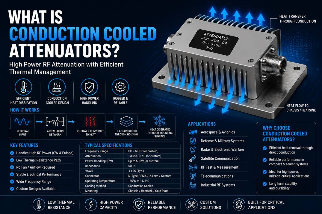
Conduction cooled attenuators are specialized RF and microwave components designed to reduce signal power while efficiently transferring the heat generated by RF power dissipation into a conductive thermal path such as a chassis, heatsink, cold plate, or mounting structure.
A conventional RF attenuator absorbs a portion of the RF signal and converts that energy into heat. As RF power increases, thermal management becomes increasingly important. If the generated heat cannot be removed efficiently, the attenuator may experience excessive temperature rise, performance degradation, thermal drift, or permanent damage.
A conduction cooled attenuator solves this challenge by providing a designed thermal path from the internal resistive attenuation elements to the equipment’s mounting surface. Instead of depending primarily on airflow, fans, or liquid cooling, the heat is transferred through direct physical conduction.
These attenuators are particularly valuable in applications where forced-air cooling is undesirable, unavailable, or impractical. Typical applications include aerospace electronics, defense systems, radar, satellite communication, electronic warfare, high-power RF equipment, test systems, and compact microwave assemblies.
For RF system manufacturers and suppliers such as SRFS Teleinfra, conduction cooled attenuators provide an important solution for applications requiring controlled RF attenuation together with efficient thermal management.
What Is a Conduction Cooled Attenuator?
A conduction cooled attenuator is an RF attenuator engineered to dissipate heat through a conductive mechanical interface.
An RF attenuator reduces the amplitude of an RF signal by a specified amount, typically expressed in decibels (dB). The energy removed from the RF signal is converted primarily into heat within the attenuator’s resistive network.
In a conduction cooled design, this heat is transferred from the resistive elements through the attenuator’s internal thermal structure and housing into the equipment chassis or dedicated cooling surface.
The basic thermal path can be represented as:
RF Signal → Resistive Attenuation Elements → Thermal Structure → Attenuator Housing → Mounting Interface → Chassis/Cold Plate/Heatsink
This thermal architecture enables the attenuator to handle substantial RF power within systems where airflow is limited.
Why Are Conduction Cooled Attenuators Required?
RF power generates heat whenever it is dissipated by a resistive component.
For example, a 100 W RF signal passing through a 10 dB attenuator does not simply disappear at the output. Ideally, approximately 90% of the input power is dissipated inside the attenuator while approximately 10% reaches the output.
Therefore:
Input Power = 100 W
10 dB attenuation means approximately:
Output Power = 10 W
Dissipated Power = 90 W
The exact thermal behavior depends on frequency, impedance matching, VSWR, construction, duty cycle, temperature, and RF waveform.
At high power levels, removing this dissipated heat becomes a critical part of RF system design.
How Does a Conduction Cooled Attenuator Work?
The operation involves both RF attenuation and thermal conduction.
Step 1: RF Signal Enters the Attenuator
The RF signal enters through an RF connector, transmission-line interface, or integrated RF structure.
Step 2: RF Energy Passes Through the Attenuation Network
The internal resistive network creates a controlled loss in the RF signal.
Step 3: A Portion of RF Power Is Converted Into Heat
The energy absorbed by the attenuator is converted into thermal energy.
Step 4: Heat Moves Through the Internal Thermal Path
The attenuator is designed so that heat can move efficiently from the resistive elements toward the external housing.
Step 5: Heat Transfers Into the Mounting Structure
The housing is mechanically connected to a conductive thermal surface such as a chassis, heatsink, cold plate, or equipment base.
Step 6: The Equipment Removes the Heat
The connected thermal structure carries the heat away from the attenuator and distributes it through the larger cooling system.
This approach makes conduction cooling particularly useful in sealed or compact electronic systems.
Conduction Cooling vs Air Cooling
Conduction cooled attenuators differ from conventional components that depend primarily on airflow.
| Feature | Conduction Cooled | Air Cooled |
|---|---|---|
| Primary heat path | Solid thermal interface | Airflow |
| Fan required | Usually not | May be required |
| Sealed enclosure | Highly suitable | More difficult |
| Mechanical mounting | Critical | Less critical |
| Thermal interface | Important | Less dominant |
| Vibration environment | Suitable | Fan systems may be less desirable |
| Aerospace applications | Highly suitable | Application dependent |
| Maintenance | Low | Fan maintenance may be required |
Conduction cooling is especially useful when the equipment enclosure must remain sealed against dust, moisture, contaminants, or environmental conditions.
Key Components of a Conduction Cooled Attenuator
A conduction cooled attenuator typically contains several important functional and mechanical elements.
RF Attenuation Network
The attenuation network determines how much RF power is reduced.
Common attenuation values can include:
- 1 dB
- 2 dB
- 3 dB
- 6 dB
- 10 dB
- 20 dB
- 30 dB
- Higher custom attenuation values
The available values depend on the attenuator design and application.
RF Transmission Structure
The transmission structure maintains controlled RF impedance and provides the required signal path.
Most RF and microwave attenuators are designed around a nominal 50-ohm impedance.
Thermal Conductive Structure
The thermal structure provides a low-resistance path between the RF dissipative elements and the external mounting surface.
Housing
The housing provides mechanical protection and forms an important portion of the thermal path.
Mounting Interface
The mounting surface is critical because it transfers heat into the customer’s chassis, heatsink, cold plate, or thermal management structure.
Understanding RF Attenuation
RF attenuation describes the reduction in signal power.
It is normally expressed in decibels.
The relationship between input and output power is:
Attenuation (dB) = 10 log10(Pin/Pout)
For a voltage ratio under equal impedance conditions:
Attenuation (dB) = 20 log10(Vin/Vout)
Examples include:
| Attenuation | Approximate Output Power from 100 W Input |
|---|---|
| 1 dB | 79.4 W |
| 3 dB | 50 W |
| 6 dB | 25.1 W |
| 10 dB | 10 W |
| 20 dB | 1 W |
| 30 dB | 0.1 W |
The difference between input and output power represents the power that must be dissipated, subject to the actual RF system and component characteristics.
Power Handling in Conduction Cooled Attenuators
Power handling is one of the most important specifications for a conduction cooled attenuator.
However, power rating should not be interpreted as a single universal number.
Actual power handling depends on:
- Frequency
- Ambient temperature
- Mounting surface temperature
- Thermal interface
- Duty cycle
- RF waveform
- Attenuation value
- VSWR
- Pulse characteristics
- Housing design
- Thermal resistance
- Cooling system
A component rated for a certain RF power under one thermal condition may have a different permissible power level under another condition.
Continuous Wave Power Handling
Continuous wave (CW) applications apply RF power continuously or for long periods.
In CW operation, thermal equilibrium becomes particularly important.
The attenuator must continuously transfer the generated heat to the mounting structure without exceeding its maximum allowable temperature.
This makes thermal resistance and mounting conditions critical design parameters.
Pulsed RF Power Handling
Some defense, radar, and communication systems operate with pulsed RF signals.
A pulsed attenuator may experience high instantaneous RF power while having a lower average power because the signal is active only for part of the operating cycle.
Important parameters include:
- Peak power
- Average power
- Pulse width
- Pulse repetition frequency
- Duty cycle
- Rise and fall times
A conduction cooled attenuator designed for pulsed RF applications must be evaluated according to both peak electrical stress and average thermal loading.
Thermal Management in Conduction Cooled Attenuators
Thermal management is the defining feature of conduction cooled attenuators.
The objective is to minimize the temperature rise between the RF dissipative element and the final heat sink.
A simplified thermal relationship is:
Temperature Rise = Dissipated Power × Thermal Resistance
Where thermal resistance is typically expressed in °C/W.
For example, if an attenuator dissipates 100 W and the effective thermal resistance from the heat-generating region to the cooling structure is 0.5 °C/W, the theoretical temperature rise associated with that thermal path is approximately:
100 W × 0.5 °C/W = 50 °C
Actual system temperature depends on the complete thermal path and boundary conditions.
Importance of Thermal Interface
The physical interface between the attenuator and the cooling chassis can have a major influence on performance.
Poor mechanical contact can create additional thermal resistance.
Factors that can affect thermal transfer include:
- Surface flatness
- Contact pressure
- Surface finish
- Mounting screw configuration
- Thermal interface material
- Contact area
- Chassis material
- Mounting location
For high-power applications, the mounting interface should therefore be treated as part of the attenuator’s thermal design rather than as a simple mechanical attachment.
Thermal Interface Materials
Depending on the system, thermal interface materials may be used between the attenuator and the cooling surface.
Possible solutions include:
- Thermal pads
- Thermal grease
- Thermally conductive compounds
- Thermal interface films
- Direct metal-to-metal interfaces
The correct material depends on temperature, mechanical requirements, electrical isolation requirements, surface finish, and system thermal resistance.
Conduction Cooled Attenuator Materials
Material selection affects both RF performance and thermal performance.
Common material considerations include:
Aluminum
Aluminum is lightweight and provides useful thermal conductivity, making it attractive for aerospace and compact equipment.
Copper
Copper provides excellent thermal conductivity and can be used where thermal performance is a major priority.
Copper Alloys
Copper alloys can provide a balance between mechanical strength, conductivity, machinability, and RF performance.
Plated Materials
Surface plating may be used to improve corrosion resistance, conductivity, solderability, or RF contact performance.
The final material selection depends on the frequency range, thermal requirements, environmental conditions, and manufacturing process.
RF Performance Specifications
A conduction cooled attenuator must provide both thermal and electrical performance.
Important RF specifications include:
Frequency Range
The frequency range defines where the attenuator meets its specified electrical performance.
Applications may range from lower RF frequencies into microwave and millimeter-wave frequencies depending on the design.
Attenuation Accuracy
Attenuation accuracy indicates how closely the actual attenuation matches the nominal value.
Insertion Loss
For a fixed attenuator, the specified attenuation itself represents the intentional signal reduction, but additional frequency-dependent losses and deviations can affect performance.
VSWR
VSWR indicates the quality of impedance matching.
Low VSWR is desirable because it reduces signal reflections and helps maintain predictable system performance.
Return Loss
Return loss provides another measurement of impedance matching and reflected RF power.
Power Rating
Power rating indicates the RF power the attenuator can safely dissipate under defined conditions.
Frequency Range of Conduction Cooled Attenuators
Conduction cooled attenuators can be designed for different frequency ranges depending on the intended application.
Potential applications include:
- RF systems
- Microwave systems
- Radar
- Satellite communication
- Defense electronics
- RF test equipment
- High-frequency instrumentation
The frequency range should always be verified from the manufacturer’s specific datasheet because mechanical construction, attenuation network design, connector type, and transmission-line geometry influence high-frequency performance.
Connectors Used With RF Attenuators
Depending on frequency and application, conduction cooled attenuators can use different RF interfaces.
Examples include:
- SMA
- N-Type
- TNC
- 2.92 mm
- 2.4 mm
- 1.85 mm
- SMP
- SMPM
- Waveguide interfaces
- Custom RF interfaces
High-frequency designs often require precision connectors or integrated interfaces to maintain low VSWR and predictable RF characteristics.
Why Conduction Cooling Is Important in Aerospace
Aerospace electronics often have strict requirements for:
- Weight
- Volume
- Reliability
- Thermal management
- Vibration resistance
- Shock resistance
- Environmental performance
- Long operational life
Fans and other active cooling systems may not always be desirable in aerospace equipment.
Conduction cooling allows heat to be transferred directly into the equipment’s structural thermal management system.
This makes conduction cooled RF components highly valuable in airborne and space-related applications.
Conduction Cooled Attenuators in Defense Systems
Defense electronics often require compact, rugged, high-power RF components.
Applications may include:
- Radar
- Electronic warfare
- RF countermeasure systems
- Tactical communication
- Electronic intelligence systems
- Signal generation
- RF power distribution
- High-power microwave equipment
These systems may operate under demanding environmental conditions where mechanical strength and thermal management are both important.
Conduction Cooled Attenuators in Radar
Radar systems can generate significant RF power, particularly in transmit chains.
Attenuators may be used for:
- Signal level control
- Calibration
- Power balancing
- Receiver protection
- Transmitter testing
- Signal conditioning
- System characterization
Because the attenuator may need to dissipate significant RF energy, conduction cooling can provide an efficient thermal management solution.
Conduction Cooled Attenuators in Satellite Communication
Satellite electronics have unique thermal management requirements.
In many space systems, traditional fan-based cooling is not practical. Heat must instead be transferred through conduction to dedicated thermal structures.
Conduction cooled attenuators can therefore be used in:
- Satellite RF payloads
- Transponders
- Microwave subsystems
- RF distribution networks
- Communication payloads
- Test and qualification systems
For space applications, additional requirements such as mass, outgassing, radiation, vibration, thermal cycling, and qualification may also become important.
Conduction Cooled Attenuators for Electronic Warfare
Electronic warfare systems can involve high-power RF signals and compact electronics.
Attenuators may be used for:
- RF signal conditioning
- Power control
- Test systems
- Calibration
- Receiver protection
- Signal routing
- RF subsystem development
Conduction cooling can help integrate high-power RF components into compact and rugged electronic architectures.
Conduction Cooled Attenuators for RF Test Equipment
RF test and measurement equipment often requires highly predictable signal levels.
Attenuators are used in:
- Signal generators
- Spectrum analyzers
- Network analyzers
- RF power testing
- Amplifier testing
- Calibration systems
Conduction cooled designs can be useful when the test equipment must dissipate significant RF power within a compact enclosure.
Fixed vs Variable Conduction Cooled Attenuators
Fixed Attenuators
A fixed attenuator provides a predetermined attenuation value.
Examples include:
- 3 dB
- 6 dB
- 10 dB
- 20 dB
- 30 dB
Fixed attenuators are commonly used where a stable and predictable signal reduction is required.
Variable Attenuators
Variable attenuators allow the attenuation level to be changed.
They can be implemented using mechanical, electronic, or semiconductor-based architectures depending on the application.
Variable conduction cooled designs may require additional thermal and electrical considerations.
Conduction Cooled vs Heat Sink Mounted Attenuators
The terms can sometimes overlap, but conduction cooled designs specifically emphasize the controlled thermal path through the component mounting interface.
A conventional heat-sink-mounted component may simply be attached to a heatsink.
A purpose-built conduction cooled attenuator is designed from the beginning around:
- Heat generation
- Internal thermal path
- Housing conductivity
- Mounting surface
- Contact resistance
- System-level heat rejection
This integrated approach is especially important for high-power RF systems.
Advantages of Conduction Cooled Attenuators
Efficient Thermal Management
Heat is transferred directly through a conductive path.
Compact Design
The absence of fans and large airflow structures can support compact equipment architectures.
Suitable for Sealed Systems
Conduction cooling works well in sealed electronic enclosures.
Improved Environmental Protection
A sealed enclosure can reduce exposure to dust, moisture, contaminants, and other environmental factors.
High Reliability
Removing moving cooling components such as fans can reduce the number of mechanical failure points.
Aerospace Compatibility
Conduction cooling is well suited to applications where weight, volume, vibration, and thermal management are important.
Low Maintenance
A passive thermal path generally requires less maintenance than active fan-based cooling.
Limitations of Conduction Cooled Attenuators
Conduction cooling also has limitations.
Mounting Is Critical
Poor mechanical contact can increase thermal resistance.
Chassis Temperature Matters
The attenuator’s ability to dissipate heat depends partly on the temperature of the connected cooling structure.
System-Level Thermal Design Is Required
The component cannot be evaluated independently from its cooling environment.
High Power Requires Careful Analysis
High RF power can generate substantial heat, requiring detailed thermal calculations and sometimes simulation.
Conduction Cooled Attenuator Design Considerations
When designing or selecting a conduction cooled attenuator, engineers should evaluate:
- RF frequency
- Nominal impedance
- Attenuation value
- Attenuation accuracy
- VSWR
- Return loss
- Continuous power
- Peak power
- Pulse width
- Duty cycle
- Operating temperature
- Storage temperature
- Thermal resistance
- Mounting surface temperature
- Housing material
- Connector type
- Mechanical dimensions
- Weight
- Environmental requirements
- Reliability requirements
How to Select the Right Conduction Cooled Attenuator
1. Determine the Frequency Range
Select an attenuator whose specified frequency range covers the complete operating band.
2. Determine the Required Attenuation
Choose the required dB value based on the RF system’s power and signal-level requirements.
3. Calculate Dissipated Power
Estimate how much RF power will be converted into heat.
For a 10 dB attenuator, approximately 90% of the incident power is dissipated under an ideal matched condition.
4. Determine Continuous and Peak Power
For pulsed applications, evaluate both peak and average power.
5. Evaluate Thermal Resistance
Check the thermal resistance from the heat-generating region to the mounting interface.
6. Verify the Cooling Surface
Ensure that the chassis or heatsink can maintain an appropriate temperature under the expected load.
7. Check RF Performance
Review:
- VSWR
- Return loss
- Attenuation accuracy
- Frequency response
- Power handling
8. Verify Mechanical Compatibility
Check mounting dimensions, hole patterns, connector orientation, package size, and available installation space.
9. Evaluate Environmental Requirements
For aerospace and defense applications, consider vibration, shock, humidity, temperature cycling, and other environmental requirements.
Example of Conduction Cooled Attenuator Power Calculation
Suppose an RF system delivers 200 W to a 10 dB attenuator.
For an ideal matched attenuator:
Output power:
200 W × 0.1 = 20 W
Approximately:
200 W − 20 W = 180 W
is dissipated as heat.
Therefore, the thermal system must be capable of removing approximately 180 W of heat under the specified operating conditions.
This example demonstrates why thermal design becomes extremely important as attenuation and input power increase.
Conduction Cooled Attenuator vs Conventional RF Attenuator
| Parameter | Conduction Cooled Attenuator | Conventional RF Attenuator |
|---|---|---|
| RF attenuation | Yes | Yes |
| Heat generation | Yes | Yes |
| Dedicated conductive thermal path | Yes | May vary |
| Chassis mounting importance | Very high | Moderate |
| High-power applications | Excellent for suitable designs | Application dependent |
| Sealed equipment | Highly suitable | Depends on cooling design |
| Aerospace use | Common design approach | Application dependent |
| Thermal interface | Critical | May be less critical |
| Active airflow | Usually not required | May be used |
Applications of Conduction Cooled Attenuators
Conduction cooled attenuators can be used in a wide range of RF and microwave systems.
Aerospace
Used in airborne RF electronics and compact high-performance communication systems.
Defense
Used in radar, electronic warfare, communication, and RF test systems.
Satellite Communication
Used in satellite payloads, RF distribution, transponders, and microwave subsystems.
Radar
Used for power control, calibration, receiver protection, and RF signal conditioning.
Electronic Warfare
Used for RF signal management, subsystem testing, and power control.
RF Test and Measurement
Used in signal generators, power testing, calibration, and RF instrumentation.
Telecommunications
Used in RF signal distribution and specialized high-power communication equipment.
Industrial RF Systems
Used in high-power RF generators, heating systems, and specialized communication equipment.
Reliability of Conduction Cooled Attenuators
Reliability depends on both electrical and thermal design.
Important reliability factors include:
- Maximum component temperature
- Thermal cycling
- Mechanical stress
- RF power cycling
- Connector durability
- Material compatibility
- Mounting interface
- Environmental exposure
Maintaining the component within its specified temperature range is particularly important for long-term reliability.
Testing of Conduction Cooled Attenuators
A professional conduction cooled attenuator may undergo several electrical and environmental tests.
RF Tests
Common measurements include:
- Insertion loss
- Attenuation accuracy
- Return loss
- VSWR
- Frequency response
- Power handling
Thermal Tests
Thermal evaluation may include:
- Temperature rise
- Thermal resistance
- Steady-state temperature
- Thermal cycling
- High-temperature operation
Mechanical Tests
Depending on the application:
- Vibration
- Mechanical shock
- Mounting integrity
- Connector durability
Environmental Tests
Specialized applications may require:
- Humidity testing
- Temperature cycling
- Salt atmosphere testing
- Altitude testing
- Vacuum testing
- Radiation qualification
The exact qualification program depends on the target application and industry standards.
Role of Conduction Cooling in High-Power RF Systems
As RF systems become smaller and more powerful, thermal density continues to increase.
This creates a fundamental engineering challenge:
More RF power + Smaller enclosure = Higher thermal density
Conduction cooling addresses this challenge by creating a direct heat path from the RF dissipative component to the equipment’s thermal structure.
This approach supports compact RF architectures without relying exclusively on forced-air cooling.
Why Choose a Custom Conduction Cooled Attenuator?
Standard attenuators may not always satisfy the mechanical and thermal requirements of specialized RF systems.
Custom conduction cooled attenuators can be designed around:
- Specific frequency ranges
- Custom attenuation values
- High continuous power
- Pulsed RF power
- Custom mounting patterns
- Specific connector configurations
- Restricted installation space
- Specialized thermal interfaces
- Aerospace requirements
- Defense requirements
Custom engineering can therefore be useful when standard commercial components cannot provide the required combination of RF and thermal performance.
Conduction Cooled Attenuators for SRFS Teleinfra Applications
SRFS Teleinfra can position conduction cooled attenuators as specialized RF solutions for applications requiring controlled attenuation and efficient thermal management.
Potential target industries include:
- Aerospace
- Defense
- Radar
- Satellite communication
- Telecom infrastructure
- RF testing
- Electronic warfare
- Industrial RF systems
The product specification should be selected according to the actual frequency range, attenuation value, power level, connector configuration, thermal interface, and environmental requirements.
SEO Keywords for Conduction Cooled Attenuators
Important keywords related to this topic include:
- Conduction Cooled Attenuators
- conduction cooled RF attenuator
- conduction cooled attenuator manufacturer
- conduction cooled attenuator supplier
- high power conduction cooled attenuator
- RF conduction cooled attenuator
- microwave conduction cooled attenuator
- aerospace RF attenuator
- defense RF attenuator
- high power RF attenuator
- conduction cooled microwave attenuator
- custom RF attenuator
- RF attenuator manufacturer
- RF attenuator supplier
- high power microwave attenuator
Conclusion
Conduction cooled attenuators are specialized RF components designed to provide controlled signal attenuation while transferring internally generated RF heat through a conductive thermal path.
Their thermal architecture makes them particularly useful in high-power, compact, sealed, and environmentally demanding RF systems. Instead of relying primarily on airflow, the heat generated by the attenuation network is conducted through the component housing and mounting interface into a chassis, heatsink, cold plate, or other thermal management structure.
The most important selection factors include frequency range, attenuation value, RF power handling, VSWR, return loss, attenuation accuracy, thermal resistance, mounting surface temperature, connector type, mechanical configuration, and environmental requirements.
For aerospace, defense, radar, satellite communication, electronic warfare, and high-power RF test systems, conduction cooled attenuators can provide an effective combination of RF performance, thermal management, compact construction, and system-level reliability.
Frequently Asked Questions
1. What is a conduction cooled attenuator?
A conduction cooled attenuator is an RF attenuator designed to dissipate heat through a conductive path from its internal attenuation network to a chassis, heatsink, cold plate, or other cooling structure.
2. How does a conduction cooled attenuator work?
It reduces RF signal power through a resistive attenuation network and transfers the resulting heat through the component housing and mounting interface into an external thermal structure.
3. Why is conduction cooling used in RF attenuators?
Conduction cooling provides an efficient way to remove heat without relying primarily on fans or forced airflow. It is particularly useful in compact, sealed, aerospace, defense, and high-power RF systems.
4. What is the difference between a conduction cooled and conventional attenuator?
Both attenuate RF signals, but a conduction cooled attenuator is specifically engineered with a thermal path and mounting interface for transferring heat into a cooling structure.
5. What applications use conduction cooled attenuators?
They are used in aerospace, defense, radar, satellite communication, electronic warfare, RF test equipment, telecommunications, and specialized high-power RF systems.
6. Can conduction cooled attenuators handle high RF power?
Yes, conduction cooled attenuators can be designed for high RF power applications. The actual power rating depends on frequency, thermal resistance, mounting conditions, temperature, duty cycle, and the specific component design.
7. What is thermal resistance in a conduction cooled attenuator?
Thermal resistance describes how effectively heat moves through the thermal path. Lower thermal resistance generally allows more efficient heat transfer and lower temperature rise for a given dissipated power.
8. Why is the mounting surface important?
The mounting surface forms part of the thermal path. Poor contact, inadequate cooling, or excessive chassis temperature can increase the attenuator’s operating temperature and reduce its allowable power handling.
9. Can conduction cooled attenuators be used in sealed enclosures?
Yes. Conduction cooling is particularly suitable for sealed electronic enclosures because heat can be transferred through the chassis without requiring an airflow path through the enclosure.
10. What attenuation values are available?
Conduction cooled attenuators can be designed with different attenuation values, including commonly used values such as 3 dB, 6 dB, 10 dB, 20 dB, and 30 dB. Custom attenuation values may also be possible depending on the design.
11. What is the power dissipation of a 10 dB attenuator?
Ideally, a 10 dB attenuator passes approximately 10% of the input power to the output and dissipates approximately 90% as heat under matched conditions.
12. Are conduction cooled attenuators suitable for pulsed RF?
Yes. They can be designed for pulsed RF applications, but peak power, average power, pulse width, repetition rate, and duty cycle must all be considered.
13. What RF connectors can be used?
Depending on frequency and application, conduction cooled attenuators can use SMA, N-Type, TNC, 2.92 mm, 2.4 mm, 1.85 mm, SMP, SMPM, waveguide, or custom RF interfaces.
14. What impedance is normally used?
Most RF and microwave conduction cooled attenuators are designed for a nominal 50-ohm impedance.
15. What specifications should be checked before buying a conduction cooled attenuator?
Important specifications include frequency range, attenuation, attenuation accuracy, power rating, VSWR, return loss, thermal resistance, operating temperature, mounting interface, connector type, dimensions, and environmental requirements.
16. Are conduction cooled attenuators suitable for aerospace applications?
Yes. Their passive thermal management approach and compact architecture make them well suited to many aerospace applications, subject to the required mechanical, environmental, thermal, and qualification requirements.
17. Can a conduction cooled attenuator replace a fan-cooled attenuator?
The suitability depends on the system’s thermal architecture. A conduction cooled attenuator requires an effective conductive heat path to a suitable cooling structure and cannot simply be substituted without evaluating the complete thermal design.
18. Why is thermal management important in high-power attenuators?
An attenuator converts part of the RF energy into heat. At high power levels, this heat can cause excessive temperature rise unless it is efficiently transferred away from the component.
19. What is the role of the chassis in conduction cooling?
The chassis or cold plate acts as a heat-rejection structure. Heat conducted from the attenuator enters the chassis and is subsequently distributed or removed by the system’s overall thermal management architecture.
20. Where can I use a custom conduction cooled attenuator?
Custom conduction cooled attenuators can be used in specialized aerospace, defense, radar, satellite, electronic warfare, RF test, telecom, and industrial RF applications where standard attenuators do not meet the required RF, thermal, mechanical, or environmental specifications.










