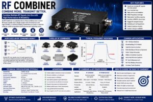
An RF Combiner is a passive radio frequency (RF) device used to combine two or more RF signals into a single output without significantly degrading signal quality. It is an essential component in modern wireless communication systems, enabling multiple transmitters or signal sources to share a common antenna while maintaining high isolation and minimal insertion loss.
RF Combiners are widely used in telecommunications, broadcasting, 4G LTE, 5G infrastructure, satellite communication, public safety networks, military communication, industrial wireless systems, and RF testing laboratories. By combining multiple RF signals into one transmission path, these devices reduce equipment costs, simplify antenna installations, improve spectrum utilization, and optimize network performance.
Modern RF Combiners are designed to operate across a broad frequency range, from low-frequency communication systems to high-frequency microwave and millimeter-wave applications. Depending on the design, they can combine signals operating in the same frequency band or in different frequency bands while maintaining excellent isolation and impedance matching.
This comprehensive guide explains everything about RF Combiners, including their working principle, construction, types, specifications, applications, advantages, and selection criteria.
What Is an RF Combiner?
An RF Combiner is a passive RF component that merges multiple radio frequency input signals into a single output port. It enables several transmitters or RF sources to share one antenna or transmission line while minimizing signal interference and maintaining proper impedance.
Unlike a power divider, which splits one input signal into multiple outputs, an RF Combiner performs the opposite function by combining several input signals into one output.
RF Combiners are available in various configurations, including two-way, three-way, four-way, and multi-port designs, depending on the number of input signals and system requirements.
How Does an RF Combiner Work?
An RF Combiner operates by receiving RF signals through multiple input ports and combining them into a single output using an internal network of transmission lines, transformers, hybrid couplers, or resonant circuits.
The operating process includes:
- Multiple RF signals enter separate input ports.
- Internal combining circuits merge the signals.
- Proper impedance matching minimizes reflections.
- High isolation reduces interaction between input ports.
- The combined RF signal exits through a single output connector.
- The output is transmitted to an antenna or RF system.
High-quality RF Combiners maintain low insertion loss and excellent isolation, ensuring reliable communication and efficient signal transmission.
Construction of an RF Combiner
Input Ports
The input ports receive RF signals from transmitters, amplifiers, or communication equipment.
Common connector types include:
- SMA
- N-Type
- BNC
- TNC
- 7/16 DIN
- 4.3-10
Combining Network
The combining network merges multiple RF signals while maintaining impedance and isolation.
Common technologies include:
- Wilkinson networks
- Hybrid couplers
- Transformer circuits
- Cavity resonators
- Microstrip circuits
Isolation Circuit
Isolation structures prevent RF energy from flowing back into other input ports, protecting connected equipment and reducing interference.
Output Port
The combined RF signal exits through the output connector and is transmitted to the antenna or downstream equipment.
Shielded Housing
The housing provides mechanical protection and minimizes electromagnetic interference.
Typical materials include:
- Aluminum
- Brass
- Stainless Steel
Working Principle of an RF Combiner
An RF Combiner uses carefully designed RF transmission paths to merge signals efficiently.
The operating sequence includes:
- RF signals enter separate input ports.
- Signals travel through impedance-matched combining circuits.
- Isolation networks reduce port interaction.
- Combined signal exits through the output port.
- Signal quality remains stable with low insertion loss.
This allows multiple transmitters to operate through a single antenna without causing significant interference.
Types of RF Combiners
Two-Way RF Combiner
Combines two RF input signals into one output.
Commonly used in small communication systems.
Three-Way RF Combiner
Combines three independent RF signals.
Used in wireless communication infrastructure.
Four-Way RF Combiner
Supports four transmitters sharing a common antenna.
Widely used in broadcasting and base stations.
Hybrid RF Combiner
Uses hybrid coupler technology to provide excellent isolation and low insertion loss.
Cavity RF Combiner
Uses resonant cavities to combine high-power RF signals.
Common in television, radio broadcasting, and cellular networks.
Broadband RF Combiner
Supports wide frequency ranges across multiple communication bands.
High-Power RF Combiner
Designed for high-power transmitters used in broadcasting, radar, and defense systems.
Technical Specifications
| Specification | Typical Value |
|---|---|
| Frequency Range | DC to 40 GHz (depending on model) |
| Characteristic Impedance | 50 Ohms |
| Number of Ports | 2 to 16 |
| Insertion Loss | Low |
| Isolation | 20–40 dB |
| VSWR | ≤ 1.30 |
| Power Handling | Up to Several Kilowatts |
| Connector Types | SMA, N-Type, BNC, 7/16 DIN |
| Operating Temperature | -55°C to +125°C |
| Housing Material | Aluminum, Brass, Stainless Steel |
Key Features of RF Combiners
- Low insertion loss
- High port isolation
- Excellent impedance matching
- Wide frequency range
- High power handling
- Reliable signal combining
- Rugged construction
- Compact design
- Stable RF performance
- Long service life
- Multiple connector options
- Easy integration into RF systems
Applications of RF Combiners
Cellular Base Stations
Combine multiple transmitter outputs into a shared antenna system.
5G Networks
Support multi-band and multi-carrier communication infrastructure.
Broadcasting
Combine radio and television transmitter outputs efficiently.
Satellite Communication
Merge multiple communication channels for satellite uplink systems.
Public Safety Networks
Support emergency communication systems with shared antenna infrastructure.
Military Communication
Used in tactical radio systems, radar installations, and secure communication networks.
Industrial Wireless Systems
Improve communication efficiency in factories, mining sites, and automation systems.
RF Test Laboratories
Combine multiple signal sources for testing and measurement applications.
DAS (Distributed Antenna Systems)
Support indoor wireless coverage in commercial buildings, airports, hospitals, and stadiums.
Amateur Radio
Enable multiple transmitters to share a common antenna while maintaining signal integrity.
Advantages of RF Combiners
- Reduces the number of antennas required
- Low insertion loss
- Excellent signal isolation
- Improves spectrum efficiency
- Simplifies antenna installation
- Supports multiple transmitters
- High reliability
- Compact design
- Cost-effective network deployment
- High power capability
- Long operational life
- Easy maintenance
Limitations of RF Combiners
- Insertion loss increases with more ports
- Precision models are more expensive
- Frequency-specific models have limited bandwidth
- Improper impedance matching can reduce performance
- High-power systems require careful thermal management
How to Choose the Right RF Combiner
When selecting an RF Combiner, consider the following factors:
- Operating frequency
- Number of input ports
- Power handling capability
- Connector type
- Insertion loss
- Isolation
- VSWR
- Bandwidth
- Environmental conditions
- Indoor or outdoor installation
RF Combiner vs RF Power Divider
| Feature | RF Combiner | RF Power Divider |
|---|---|---|
| Primary Function | Combines Multiple Signals | Splits One Signal |
| Signal Direction | Many Inputs to One Output | One Input to Multiple Outputs |
| Number of Ports | Two or More Inputs | Two or More Outputs |
| Applications | Shared Antenna Systems | Signal Distribution |
| Isolation | High | Moderate |
| RF Performance | Excellent | Excellent |
Industries Using RF Combiners
RF Combiners are widely used in:
- Telecommunications
- Broadcasting
- Aerospace
- Defense
- Satellite Communication
- Public Safety
- Industrial Automation
- Scientific Research
- RF Testing Laboratories
- Transportation Infrastructure
Maintenance Tips
To maximize RF Combiner performance:
- Keep connectors clean and dry.
- Inspect connectors regularly.
- Use the recommended tightening torque.
- Avoid exceeding the rated RF power.
- Protect outdoor installations with weatherproof enclosures.
- Verify insertion loss during scheduled maintenance.
- Replace damaged connectors immediately.
Future Trends of RF Combiners
The expansion of 5G Advanced, Open RAN, private 5G networks, satellite internet, smart cities, and future 6G communication systems is driving innovation in RF Combiner technology. Manufacturers are developing broadband combiners with lower insertion loss, higher isolation, improved thermal performance, and compact multi-band designs. Advanced materials, AI-assisted network optimization, and integrated RF front-end solutions will further improve efficiency, enabling RF Combiners to support higher frequencies, larger bandwidths, and increasingly complex wireless communication networks.
Conclusion
RF Combiners are essential passive components that enable multiple RF signals to be combined into a single transmission path while maintaining low insertion loss, excellent isolation, and stable impedance. They are widely used in telecommunications, broadcasting, satellite communication, military systems, public safety networks, industrial automation, and 5G infrastructure. By selecting the appropriate RF Combiner based on frequency range, number of ports, power handling, insertion loss, and connector type, engineers can improve network efficiency, reduce installation costs, and ensure reliable RF system performance.
Frequently Asked Questions (FAQs)
1. What is an RF Combiner?
An RF Combiner is a passive RF device that combines two or more radio frequency signals into a single output while maintaining signal integrity and impedance.
2. What is an RF Combiner used for?
RF Combiners are used to allow multiple transmitters or RF sources to share a common antenna in telecommunications, broadcasting, satellite communication, and wireless networks.
3. How does an RF Combiner work?
It merges multiple RF input signals through an internal combining network while minimizing insertion loss and maintaining high isolation between input ports.
4. What are the different types of RF Combiners?
Common types include Two-Way RF Combiners, Three-Way RF Combiners, Four-Way RF Combiners, Hybrid Combiners, Cavity Combiners, Broadband Combiners, and High-Power RF Combiners.
5. What frequency range do RF Combiners support?
Depending on the design, RF Combiners can operate from DC up to 40 GHz, with specialized microwave models supporting even higher frequencies.
6. What impedance is commonly used in RF Combiners?
Most RF Combiners are designed with a 50 Ohm characteristic impedance.
7. What are the advantages of an RF Combiner?
They reduce the number of antennas required, provide low insertion loss, high isolation, improved spectrum efficiency, simplified installation, and reliable RF performance.
8. Where are RF Combiners commonly used?
They are widely used in cellular base stations, 5G networks, broadcasting, satellite communication, DAS systems, military communication, industrial wireless systems, and RF laboratories.
9. What is the difference between an RF Combiner and an RF Power Divider?
An RF Combiner combines multiple input signals into one output, while an RF Power Divider splits one input signal into multiple outputs.
10. How do I choose the right RF Combiner?
Choose an RF Combiner based on operating frequency, number of input ports, power handling capability, insertion loss, isolation, VSWR, connector type, bandwidth, and the specific requirements of your RF communication system.
`