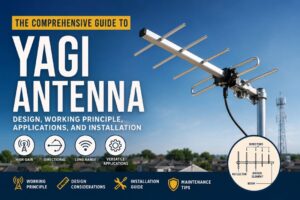
A Yagi antenna, also known as a Yagi-Uda antenna, is one of the most widely used directional antennas in telecommunications, broadcasting, wireless networking, and radio communications. Developed in the 1920s by Japanese engineers Hidetsugu Yagi and Shintaro Uda, the Yagi antenna remains a popular choice due to its high gain, excellent directivity, simple construction, and cost-effective performance.
Whether used for television reception, amateur radio, cellular signal enhancement, Wi-Fi communication, or point-to-point wireless links, Yagi antennas provide reliable long-distance communication by concentrating radio frequency (RF) energy in a specific direction.
This comprehensive guide explores the working principle, components, design considerations, advantages, disadvantages, applications, installation methods, and maintenance practices of Yagi antennas.
What is a Yagi Antenna?
A Yagi antenna is a directional antenna consisting of multiple parallel elements mounted on a conductive boom. Unlike omnidirectional antennas that radiate signals in all directions, a Yagi antenna focuses RF energy into a narrow beam, increasing signal strength and communication range.
The antenna typically consists of:
- Driven Element
- Reflector
- One or more Directors
- Supporting Boom
The combination of these elements creates constructive interference in the forward direction and destructive interference in the rear direction, resulting in high gain and directional performance.
History of the Yagi-Uda Antenna
The Yagi-Uda antenna was invented in 1926 at Tohoku Imperial University in Japan. Although Shintaro Uda conducted much of the research, Hidetsugu Yagi introduced the design internationally, leading to its widespread adoption.
The antenna gained popularity during World War II for radar systems and later became a standard solution for television reception and radio communications worldwide.
Today, Yagi antennas are used across various frequency bands ranging from HF and VHF to UHF and microwave frequencies.
Basic Components of a Yagi Antenna
1. Driven Element
The driven element is the only component directly connected to the transmitter or receiver.
Characteristics:
- Usually a half-wave dipole
- Responsible for transmitting and receiving signals
- Determines the operating frequency
Functions:
- Converts electrical signals into electromagnetic waves
- Receives incoming RF signals
2. Reflector
The reflector is placed behind the driven element.
Characteristics:
- Slightly longer than the driven element
- Reflects RF energy toward the front
Benefits:
- Improves forward gain
- Reduces rear radiation
- Enhances front-to-back ratio
3. Directors
Directors are placed in front of the driven element.
Characteristics:
- Slightly shorter than the driven element
- Multiple directors can be added
Functions:
- Focus RF energy forward
- Increase antenna gain
- Narrow beamwidth
The greater the number of directors, the higher the directional gain.
4. Boom
The boom serves as the structural support.
Functions:
- Maintains proper element spacing
- Provides mechanical stability
- Supports installation hardware
How a Yagi Antenna Works
The Yagi antenna operates using the principle of mutual coupling between antenna elements.
Step 1: Signal Generation
The driven element receives power from the transmitter or incoming signals from the air.
Step 2: Induced Currents
Electromagnetic fields induce currents in the reflector and director elements.
Step 3: Signal Reinforcement
The spacing and length of parasitic elements create phase shifts that reinforce signals in the forward direction.
Step 4: Directional Radiation
The combined effect concentrates energy into a narrow beam, producing higher gain and longer communication distances.
Radiation Pattern
A Yagi antenna produces a directional radiation pattern.
Main Lobe
The strongest signal region pointing toward the directors.
Side Lobes
Minor radiation areas located at angles to the main beam.
Back Lobe
Radiation behind the antenna, minimized by the reflector.
Front-to-Back Ratio
Measures how effectively the antenna suppresses rear signals.
Typical values range from:
- 15 dB
- 20 dB
- 30 dB or higher
Frequency Ranges of Yagi Antennas
HF Band
3 MHz – 30 MHz
Applications:
- Amateur radio
- Long-distance communication
VHF Band
30 MHz – 300 MHz
Applications:
- FM broadcasting
- Public safety communication
- Marine communication
UHF Band
300 MHz – 3 GHz
Applications:
- Television reception
- Cellular networks
- Wireless broadband
Microwave Frequencies
Above 3 GHz
Applications:
- Point-to-point links
- Radar systems
- Specialized wireless communication
Key Performance Parameters
Gain
Gain indicates signal amplification in a specific direction.
Typical values:
| Number of Elements | Gain |
|---|---|
| 3 Element | 6–8 dBi |
| 5 Element | 8–10 dBi |
| 10 Element | 10–13 dBi |
| 15+ Element | 13–18 dBi |
Beamwidth
Beamwidth measures the angular width of the main signal beam.
Narrow beamwidth:
- Higher gain
- Better directivity
Wide beamwidth:
- Easier alignment
- Lower gain
Front-to-Back Ratio
Indicates rejection of unwanted signals from behind.
Higher values provide:
- Better interference suppression
- Improved signal quality
Bandwidth
Yagi antennas generally offer moderate bandwidth.
Advantages:
- Good frequency selectivity
- Reduced interference
Limitations:
- Less suitable for very wideband applications
Advantages of Yagi Antennas
High Gain
Provides stronger signal transmission and reception.
Excellent Directionality
Focuses energy precisely toward the target location.
Long Communication Range
Suitable for distant communication links.
Cost-Effective
Simple design results in lower manufacturing costs.
Easy Construction
Can be built using readily available materials.
Low Interference
Directional pattern reduces unwanted signal reception.
Disadvantages of Yagi Antennas
Narrow Bandwidth
Performance decreases outside the design frequency.
Alignment Requirements
Must be accurately pointed toward the signal source.
Physical Size
Large versions for lower frequencies require substantial space.
Wind Loading
Long-boom designs may require reinforced mounting structures
Applications of Yagi Antennas
Television Reception
Historically used for rooftop TV antennas.
Benefits:
- Improved reception
- Better signal quality
- Reduced multipath interference
Amateur Radio
Widely used by ham radio operators.
Applications
- DX communication
- Contesting
- Satellite communication
Cellular Signal Boosters
Used in:
- Rural areas
- Remote locations
- Industrial facilities
Advantages:
- Improved call quality
- Enhanced mobile data performance
Wi-Fi and Wireless Networking
Used for:
- Point-to-point links
- Long-range wireless bridges
- Campus networking
Public Safety Communication
Supports:
- Emergency services
- Police communication
- Fire departments
Industrial Communication Systems
Used in:
- SCADA networks
- Utility monitoring
- Remote telemetry systems
Radar Systems
Yagi antennas are used in specialized radar and tracking applications.
Yagi Antenna Design Considerations
Operating Frequency
The antenna dimensions depend directly on wavelength.
Formula:
Wavelength (λ) = 300 / Frequency (MHz)
Element Length
Typical values:
- Reflector: 5% longer
- Driven Element: Reference length
- Directors: 5% shorter
Element Spacing
Common spacing:
- 0.1λ to 0.3λ
Proper spacing significantly affects gain and impedance.
Number of Directors
More directors provide:
- Higher gain
- Narrower beamwidth
- Longer boom length
Material Selection
Common materials:
- Aluminum
- Copper
- Stainless steel
Aluminum is preferred because it is lightweight and corrosion resistant.
Installation Guidelines
Site Selection
Choose locations with:
- Clear line of sight
- Minimal obstructions
- Reduced RF interference
Mounting Height
Higher installations generally provide:
- Better signal propagation
- Reduced ground losses
Polarization
Match antenna polarization to the signal source.
Horizontal Polarization
Common for:
- Television
- Many radio systems
Vertical Polarization
Common for:
- Mobile communication
- Public safety networks
Cable Selection
Use low-loss coaxial cable such as:
- RG-8
- LMR-400
- LMR-600
Long cable runs should minimize attenuation losses.
Grounding and Lightning Protection
Always install:
- Grounding rods
- Lightning arrestors
- Proper surge protection
This protects both equipment and personnel.
Maintenance and Troubleshooting
Regular Inspection
Check for:
- Loose connections
- Corrosion
- Physical damage
Cleaning
Remove:
- Dirt
- Bird nests
- Debris
Alignment Verification
Strong winds may alter antenna direction.
Periodic realignment ensures optimal performance.
Cable Testing
Inspect coaxial cables for:
- Moisture ingress
- Connector damage
- Excessive signal loss
Comparison: Yagi vs Omnidirectional Antenna
| Feature | Yagi Antenna | Omnidirectional Antenna |
| Gain | High | Low to Moderate |
| Coverage | Directional | 360 Degrees |
| Range | Long | Short to Medium |
| Interference Rejection | Excellent | Limited |
| Installation | Requires Alignment | Easier |
| Best Use | Point-to-Point Links | Area Coverage |
Future of Yagi Antennas
Despite advancements in phased arrays, MIMO systems, and smart antennas, Yagi antennas remain highly relevant due to:
- Low cost
- Proven reliability
- Simple design
- High efficiency
- Strong directional performance
Modern Yagi designs continue to support wireless broadband, IoT networks, amateur radio, industrial telemetry, and specialized communication systems.
Conclusion
The Yagi antenna is one of the most effective and widely used directional antennas in modern communication systems. Its ability to provide high gain, excellent directivity, and reliable long-range performance makes it an ideal solution for television reception, amateur radio, wireless networking, cellular signal enhancement, and industrial communication networks.
By understanding its structure, operating principles, design parameters, installation practices, and maintenance requirements, engineers and communication professionals can maximize the performance and reliability of Yagi antenna systems. Whether deployed for residential, commercial, or industrial applications, the Yagi antenna continues to be a trusted technology for focused and efficient radio frequency communication.