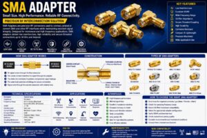
An N End Launch Adapter is a high-performance RF connector designed to provide a reliable transition between a Printed Circuit Board (PCB) transmission line and an N-Type connector interface. It is widely used in radio frequency (RF), microwave, wireless communication, aerospace, defense, satellite communication, radar systems, and laboratory testing where maintaining excellent signal integrity is essential.
Unlike standard cable connectors, an End Launch Adapter is mounted directly to the edge of a PCB, allowing RF signals to transition smoothly from the PCB transmission line into coaxial cables or external RF equipment. This design minimizes insertion loss, reduces signal reflections, and maintains controlled impedance across high-frequency circuits.
N End Launch Adapters are engineered for precision RF applications, supporting frequencies from DC to several gigahertz while offering excellent VSWR, superior shielding, and high mechanical stability. They are commonly found in RF development laboratories, 5G equipment, microwave systems, antenna testing setups, military communication equipment, and industrial wireless devices.
This comprehensive guide explains everything you need to know about N End Launch Adapters, including their construction, working principle, specifications, applications, advantages, and selection criteria.
What Is an N End Launch Adapter?
An N End Launch Adapter is a precision RF connector that mounts at the edge of a printed circuit board (PCB) and provides a transition between a microstrip or stripline PCB transmission line and a standard N-Type RF connector.
The adapter ensures that RF signals travel from the PCB to external coaxial cables with minimal signal loss and impedance mismatch.
Because N-Type connectors are known for their rugged construction, high power handling, and weather-resistant threaded coupling mechanism, N End Launch Adapters are ideal for demanding indoor and outdoor RF applications.
How Does an N End Launch Adapter Work?
An N End Launch Adapter transfers RF signals directly from a PCB transmission line into an N-Type coaxial connector.
The operation follows these steps:
- RF signals travel along the PCB transmission line.
- The PCB trace aligns with the center conductor of the End Launch Adapter.
- The adapter maintains a constant characteristic impedance.
- The RF signal enters the N-Type connector.
- The connected coaxial cable carries the signal to external equipment.
The precision alignment between the PCB trace and the connector minimizes signal reflections, insertion loss, and impedance discontinuities.
Construction of an N End Launch Adapter
N-Type Connector Interface
The connector features a threaded coupling mechanism that provides a secure mechanical connection and reliable RF performance.
Center Contact
The center pin transfers the RF signal from the PCB transmission line into the coaxial connector.
Common materials include:
- Beryllium Copper
- Brass
- Phosphor Bronze
Most contacts are gold-plated for improved conductivity and corrosion resistance.
Dielectric Insulator
The dielectric electrically isolates the center conductor from the outer body.
Common materials include:
- PTFE
- Teflon
- High-performance polymers
These materials provide excellent electrical insulation and stable impedance.
Connector Body
The connector housing is manufactured from durable materials such as:
- Stainless Steel
- Brass
- Nickel-plated Brass
These materials offer high mechanical strength and corrosion resistance.
PCB Mounting Structure
The adapter includes precision mounting flanges or solder tabs that securely attach to the PCB edge while maintaining electrical continuity.
Working Principle of an N End Launch Adapter
The adapter acts as a controlled impedance transition between planar transmission lines and coaxial RF systems.
The process includes:
- RF signal travels through the PCB trace.
- The center conductor aligns with the PCB transmission line.
- The outer connector body connects to the PCB ground plane.
- Controlled impedance minimizes reflections.
- RF energy enters the coaxial connector.
- External RF equipment receives the signal.
This design ensures stable high-frequency signal transmission with excellent return loss.
Technical Specifications
| Specification | Typical Value |
| Connector Type | N-Type Female or Male |
| Characteristic Impedance | 50 Ohms |
| Frequency Range | DC to 11 GHz (Typical) |
| VSWR | ≤ 1.20 |
| Insertion Loss | Very Low |
| Contact Material | Beryllium Copper / Brass |
| Contact Plating | Gold |
| Body Material | Stainless Steel / Brass |
| Dielectric | PTFE |
| Mounting Style | PCB End Launch |
Key Features of N End Launch Adapters
- Precision PCB mounting
- Low insertion loss
- Excellent impedance matching
- High-frequency capability
- Rugged threaded connector
- High power handling
- Superior shielding performance
- Excellent return loss
- Corrosion-resistant construction
- Easy PCB integration
- Long operational life
- Reliable mechanical stability
Types of N End Launch Adapters
N Female End Launch Adapter
Designed for direct connection with N Male RF connectors.
N Male End Launch Adapter
Used for mating with N Female RF interfaces.
Straight End Launch Adapter
Provides a straight RF transition from the PCB to the coaxial connector.
Right-Angle End Launch Adapter
Ideal for compact PCB layouts with limited installation space.
Flange Mount End Launch Adapter
Offers enhanced mechanical support for high-vibration environments.
Applications of N End Launch Adapters
RF Development
Used in prototype RF circuit boards and evaluation kits.
Microwave Communication
Supports microwave amplifiers, filters, and transceiver modules.
5G Infrastructure
Connects RF PCB modules with external antennas and test equipment.
Antenna Testing
Provides accurate RF transitions for antenna measurement systems.
Satellite Communication
Used in ground stations, RF front-end modules, and satellite terminals.
Aerospace
Supports avionics, communication systems, and navigation equipment.
Military and Defense
Used in radar systems, secure communication devices, and electronic warfare equipment.
Wireless Communication
Supports Wi-Fi, LTE, and cellular communication hardware.
Laboratory Testing
Used with:
- Network Analyzers
- Spectrum Analyzers
- Signal Generators
- RF Test Fixtures
Industrial Automation
Supports industrial wireless systems and IoT communication modules.
Advantages of N End Launch Adapters
- Excellent RF performance
- Stable impedance
- Low VSWR
- High mechanical durability
- Easy PCB installation
- Secure threaded connection
- Low signal reflection
- High-frequency operation
- Long service life
- Excellent shielding effectiveness
- Reliable laboratory performance
- Suitable for high-power RF systems
Limitations of N End Launch Adapters
- Larger than SMA End Launch connectors
- Requires accurate PCB layout
- Higher cost than standard PCB connectors
- Limited to compatible PCB thicknesses
- Proper mounting is essential for optimal RF performance
How to Choose the Right N End Launch Adapter
Before selecting an N End Launch Adapter, consider:
- Operating frequency
- PCB thickness
- Characteristic impedance
- Connector gender
- Mounting style
- Return loss
- Insertion loss
- Power handling
- Material quality
- Environmental requirements
N End Launch Adapter vs SMA End Launch Adapter
| Feature | N End Launch Adapter | SMA End Launch Adapter |
| Connector Size | Large | Compact |
| Frequency Range | Up to 11 GHz | Up to 26.5 GHz or Higher |
| Power Handling | Higher | Moderate |
| Thread Strength | Excellent | Good |
| Outdoor Use | Excellent | Moderate |
| Typical Applications | Base Stations, Radar | RF Modules, PCB Testing |
Industries Using N End Launch Adapters
N End Launch Adapters are widely used in:
- Telecommunications
- 5G Infrastructure
- Aerospace
- Defense
- Satellite Communication
- Broadcasting
- Industrial Automation
- Medical Electronics
- Scientific Research
- RF Test Laboratories
Maintenance Tips
To ensure long-term performance:
- Keep connector interfaces clean.
- Avoid excessive connector torque.
- Inspect gold-plated contacts regularly.
- Protect connectors from dust and moisture.
- Verify PCB solder joints periodically.
- Use proper RF torque wrenches.
- Replace damaged connectors immediately.
Future Trends of N End Launch Adapters
The growth of 5G Advanced, Open RAN, satellite communication, industrial IoT, and emerging 6G technologies is increasing demand for high-performance PCB RF interconnects. Manufacturers are developing N End Launch Adapters with improved impedance control, lower insertion loss, enhanced shielding, and higher durability. Advanced materials, precision CNC machining, and optimized PCB transition designs are enabling these adapters to support increasingly complex RF and microwave systems while maintaining excellent signal integrity.
Conclusion
N End Launch Adapters provide a reliable and efficient solution for connecting high-frequency PCB circuits to N-Type coaxial interfaces. Their precision design, controlled impedance, low insertion loss, and robust mechanical construction make them ideal for telecommunications, aerospace, defense, satellite communication, RF testing, and industrial wireless applications. Selecting the correct adapter based on frequency, PCB thickness, connector type, and environmental requirements ensures outstanding RF performance and long-term system reliability.
Frequently Asked Questions (FAQs)
1. What is an N End Launch Adapter?
An N End Launch Adapter is a PCB-mounted RF connector that provides a controlled impedance transition between a printed circuit board transmission line and an N-Type coaxial connector.
2. What is an N End Launch Adapter used for?
It is used in RF circuit boards, microwave systems, antenna testing, laboratory equipment, telecommunications, aerospace, and defense applications.
3. What impedance does an N End Launch Adapter have?
Most N End Launch Adapters are designed with a 50 Ohm characteristic impedance.
4. What frequency range does an N End Launch Adapter support?
Typical models operate from DC up to 11 GHz, while specialized versions may support higher frequencies.
5. What materials are used in N End Launch Adapters?
Common materials include stainless steel or brass bodies, gold-plated beryllium copper contacts, and PTFE dielectric insulation.
6. What are the advantages of an N End Launch Adapter?
They offer low insertion loss, excellent impedance matching, secure threaded connections, high power handling, rugged construction, and reliable RF performance.
7. What is the difference between an N End Launch Adapter and an SMA End Launch Adapter?
N End Launch Adapters are larger, handle higher RF power, and are better suited for outdoor and industrial applications, while SMA End Launch Adapters are smaller and commonly used in compact RF modules and laboratory equipment.
8. Where are N End Launch Adapters commonly used?
They are widely used in 5G infrastructure, satellite communication, aerospace, military systems, RF laboratories, antenna testing, and wireless communication equipment.
9. Can N End Launch Adapters be used outdoors?
Yes. Their threaded coupling design and rugged construction make them suitable for outdoor RF installations when used with appropriate environmental sealing.
10. How do I choose the right N End Launch Adapter?
Select an adapter based on operating frequency, PCB thickness, impedance, connector gender, insertion loss, return loss, power handling, mounting style, and environmental conditions.