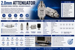
A 2.0mm Attenuator is a high-precision radio frequency (RF) and microwave component designed to reduce signal power without significantly affecting the signal waveform or introducing distortion. It is commonly used in high-frequency testing, communication systems, satellite technology, aerospace, defense, radar, and laboratory environments where accurate signal control is essential.
The 2.0mm interface is one of the industry’s precision RF connector standards, capable of supporting extremely high frequencies while maintaining excellent impedance matching and low Voltage Standing Wave Ratio (VSWR). Due to its superior mechanical accuracy and electrical performance, 2.0mm attenuators are widely used in vector network analyzers, spectrum analyzers, signal generators, and advanced microwave systems.
As wireless communication evolves toward 5G, 6G, millimeter-wave technologies, autonomous vehicles, satellite internet, and aerospace applications, the demand for precision RF attenuators continues to increase. A 2.0mm attenuator ensures stable signal levels, protects sensitive equipment, improves measurement accuracy, and enhances overall RF system performance.
This comprehensive guide explains everything you need to know about 2.0mm Attenuators, including their working principle, construction, types, specifications, applications, advantages, and selection criteria.
What Is a 2.0mm Attenuator?
A 2.0mm Attenuator is a precision RF attenuation device equipped with 2.0mm coaxial connectors that reduces the power level of microwave signals while maintaining a constant characteristic impedance, typically 50 Ohms.
Unlike amplifiers, which increase signal strength, attenuators intentionally decrease signal amplitude by a specified value measured in decibels (dB). This controlled reduction helps protect receivers, balance signal levels, improve impedance matching, and ensure accurate RF measurements.
2.0mm attenuators are designed for high-frequency operation and are capable of supporting frequencies up to 50 GHz and, in precision laboratory models, even higher.
How Does a 2.0mm Attenuator Work?
A 2.0mm Attenuator works by converting a portion of the RF signal energy into heat through a precisely designed internal resistive network.
When an RF signal enters the attenuator:
- The signal enters through the input connector.
- Internal precision resistors absorb part of the signal power.
- The remaining signal exits through the output connector.
- Characteristic impedance remains constant.
- Signal quality and waveform are preserved.
The attenuation value remains fixed or adjustable depending on the attenuator design.
Construction of a 2.0mm Attenuator
2.0mm Precision Connectors
The attenuator uses precision 2.0mm connectors designed for extremely high-frequency microwave applications.
These connectors provide:
- Excellent impedance matching
- Low reflection
- High repeatability
- Precision mechanical alignment
Resistive Attenuation Network
The internal attenuation circuit consists of precision thin-film resistors arranged in:
- Pi Network
- T Network
- Bridged T Network
These networks provide accurate attenuation while maintaining low VSWR.
Dielectric Insulation
High-performance dielectric materials provide electrical insulation and mechanical stability.
Common materials include:
- PTFE
- Air dielectric
- Ceramic insulators
Metal Housing
The housing provides mechanical protection and electromagnetic shielding.
Common materials include:
- Stainless Steel
- Brass
- Passivated Steel
- Aluminum Alloy
Gold-Plated Contacts
Gold-plated conductors improve conductivity and resist corrosion during repeated mating cycles.
Working Principle of a 2.0mm Attenuator
The attenuation process follows these steps:
- RF signal enters the attenuator.
- Precision resistor network absorbs part of the energy.
- Remaining RF signal passes through.
- Output signal level is reduced by the specified attenuation value.
- Signal impedance remains constant.
- Minimal signal distortion occurs.
This process enables accurate signal conditioning without affecting frequency characteristics.
Types of 2.0mm Attenuators
Fixed 2.0mm Attenuator
Provides a constant attenuation value such as:
- 3 dB
- 6 dB
- 10 dB
- 20 dB
- 30 dB
- 40 dB
Widely used in RF laboratories and communication systems.
Variable 2.0mm Attenuator
Allows engineers to manually adjust signal attenuation according to testing requirements.
Programmable Attenuator
Electronically controlled attenuation for automated RF testing and measurement systems.
High-Power 2.0mm Attenuator
Designed for applications requiring high RF power dissipation while maintaining signal accuracy.
Precision Laboratory Attenuator
Manufactured with extremely tight tolerances for calibration and metrology applications.
Technical Specifications
| Specification | Typical Value |
| Connector Type | 2.0mm Male/Female |
| Characteristic Impedance | 50 Ohms |
| Frequency Range | DC to 50 GHz |
| Attenuation Values | 1 dB to 40 dB |
| VSWR | ≤ 1.20 |
| Power Rating | 1 W to 50 W |
| Return Loss | Excellent |
| Body Material | Stainless Steel / Brass |
| Operating Temperature | -55°C to +125°C |
| RoHS Compliance | Yes |
Common Attenuation Values
The most commonly available attenuation levels include:
- 1 dB
- 2 dB
- 3 dB
- 5 dB
- 6 dB
- 10 dB
- 15 dB
- 20 dB
- 30 dB
- 40 dB
Custom attenuation values are also available for specialized applications.
Applications of 2.0mm Attenuators
RF Test Laboratories
Used with:
- Vector Network Analyzers
- Spectrum Analyzers
- Signal Generators
- RF Calibration Equipment
Satellite Communication
Controls microwave signal levels in satellite ground stations.
5G Infrastructure
Supports millimeter-wave testing and network optimization.
Aerospace
Used in aircraft communication systems and microwave testing.
Defense
Supports radar systems, electronic warfare, and military communication equipment.
Microwave Communication
Provides signal conditioning in microwave transmission systems.
Semiconductor Testing
Used during wafer-level RF testing and device characterization.
Scientific Research
Supports universities, laboratories, and research institutions.
Medical Equipment
Used in MRI systems and RF diagnostic equipment.
Manufacturing
Supports RF production testing and quality assurance.
Advantages of 2.0mm Attenuators
- Extremely accurate attenuation
- Wide frequency coverage
- Low insertion loss beyond specified attenuation
- Excellent impedance matching
- Low VSWR
- High repeatability
- Precision microwave performance
- Rugged construction
- Excellent shielding
- Long service life
- Easy integration
- Reliable laboratory measurements
Limitations of 2.0mm Attenuators
- Higher cost than standard RF attenuators
- Requires precision connectors
- Sensitive to connector contamination
- Limited compatibility with larger RF connector interfaces without adapters
- High-frequency models require careful handling
How to Choose the Right 2.0mm Attenuator
When selecting a 2.0mm Attenuator, evaluate:
- Operating frequency
- Required attenuation value
- Power handling capability
- VSWR specification
- Connector gender
- Mechanical durability
- Environmental conditions
- Calibration requirements
- Return loss performance
- Application type
2.0mm Attenuator vs SMA Attenuator
| Feature | 2.0mm Attenuator | SMA Attenuator |
| Maximum Frequency | Up to 50 GHz | Up to 18–26.5 GHz |
| Precision | Very High | High |
| VSWR | Lower | Moderate |
| Laboratory Accuracy | Excellent | Good |
| Mechanical Tolerance | Precision Grade | Standard |
| Cost | Higher | Lower |
| Applications | Microwave Testing | General RF Systems |
Industries Using 2.0mm Attenuators
2.0mm Attenuators are widely used in:
- Telecommunications
- Aerospace
- Defense
- Satellite Communication
- Semiconductor Manufacturing
- Scientific Research
- Medical Electronics
- RF Calibration Laboratories
- Microwave Engineering
- 5G and 6G Development
Maintenance Tips
To maximize the life and accuracy of a 2.0mm Attenuator:
- Keep connectors clean using approved RF cleaning tools.
- Avoid over-tightening precision connectors.
- Use the recommended torque wrench.
- Protect connector interfaces with dust caps.
- Store in a clean, dry environment.
- Inspect connectors before every measurement.
- Perform periodic calibration for critical applications.
Future Trends of 2.0mm Attenuators
The expansion of millimeter-wave communication, 5G Advanced, 6G research, satellite internet, quantum computing, aerospace systems, and high-speed semiconductor testing is driving innovation in precision RF attenuators. Future 2.0mm attenuators will feature lower insertion loss, higher power handling, broader frequency support beyond 67 GHz, improved thermal management, and advanced thin-film resistor technologies. These improvements will help engineers achieve more accurate RF measurements and support next-generation communication and microwave technologies.
Conclusion
A 2.0mm Attenuator is a critical RF component for controlling signal power in high-frequency microwave systems without compromising signal integrity. Its precision construction, excellent impedance matching, low VSWR, and broad frequency capability make it indispensable for RF laboratories, aerospace, defense, satellite communication, semiconductor testing, and advanced wireless communication systems. Choosing the appropriate attenuation value, frequency range, connector configuration, and power rating ensures accurate measurements, reliable equipment protection, and optimal RF system performance.
Frequently Asked Questions (FAQs)
1. What is a 2.0mm Attenuator?
A 2.0mm Attenuator is a precision RF device with 2.0mm connectors that reduces microwave signal power while maintaining constant impedance and signal quality.
2. What is a 2.0mm Attenuator used for?
It is used in RF testing, satellite communication, aerospace, defense, microwave systems, 5G infrastructure, semiconductor testing, and laboratory measurements.
3. What frequency range does a 2.0mm Attenuator support?
Most standard 2.0mm attenuators support frequencies from DC up to 50 GHz, while some precision models can operate at even higher frequencies.
4. What impedance does a 2.0mm Attenuator have?
Most 2.0mm attenuators are designed with a 50 Ohm characteristic impedance.
5. What attenuation values are available?
Common values include 1 dB, 2 dB, 3 dB, 5 dB, 6 dB, 10 dB, 20 dB, 30 dB, and 40 dB.
6. What are the advantages of a 2.0mm Attenuator?
It provides precise attenuation, excellent impedance matching, low VSWR, high-frequency performance, reliable signal conditioning, and long-term stability.
7. Which industries commonly use 2.0mm Attenuators?
They are widely used in telecommunications, aerospace, defense, satellite communication, semiconductor manufacturing, scientific research, medical electronics, and RF calibration laboratories.
8. Can a 2.0mm Attenuator handle high RF power?
Yes. High-power versions are available with power ratings ranging from 1 Watt to 50 Watts or more, depending on the design.
9. What is the difference between a 2.0mm Attenuator and an SMA Attenuator?
A 2.0mm Attenuator supports much higher frequencies and offers greater measurement accuracy than a standard SMA attenuator, making it ideal for precision microwave applications.
10. How do I choose the right 2.0mm Attenuator?
Choose based on operating frequency, attenuation value, power rating, VSWR, connector type, impedance, environmental conditions, and the accuracy requirements of your RF application.