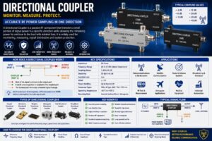
A Directional Coupler is an essential passive radio frequency (RF) and microwave component used to sample, split, monitor, or combine RF signals without significantly affecting the primary transmission path. It is one of the most widely used devices in wireless communication systems, satellite communication, broadcasting, radar, military electronics, laboratory testing, and 5G infrastructure.
Modern RF systems require precise monitoring of transmitted power, reflected power, insertion loss, and impedance matching. A Directional Coupler enables engineers to extract a controlled portion of the RF signal while allowing the majority of the signal to continue toward the load with minimal loss. This capability makes directional couplers indispensable in RF measurement, signal distribution, power monitoring, antenna testing, and communication system optimization.
Unlike ordinary power splitters, Directional Couplers are designed to transfer RF energy in only one direction. This directional property allows engineers to distinguish between forward and reflected signals, making them highly valuable for VSWR measurements, transmitter protection, and RF diagnostics.
As wireless technologies continue evolving with 5G, satellite internet, IoT, aerospace communication, and advanced radar systems, Directional Couplers remain critical components for ensuring efficient, stable, and high-performance RF signal transmission.
This comprehensive guide explains everything about Directional Couplers, including their working principle, construction, specifications, types, applications, advantages, and selection criteria.
What Is a Directional Coupler?
A Directional Coupler is a passive RF component that transfers a predetermined portion of electromagnetic energy from one transmission line to another while allowing the remaining power to continue along the main signal path.
It consists of four ports:
- Input Port
- Output Port
- Coupled Port
- Isolated Port
The input port receives the RF signal, the output port delivers most of the signal to the load, the coupled port samples a fixed percentage of the signal, and the isolated port minimizes unwanted signal leakage.
Directional Couplers are available in various coupling values such as 3 dB, 6 dB, 10 dB, 20 dB, 30 dB, and 40 dB depending on the application.
How Does a Directional Coupler Work?
A Directional Coupler operates by using electromagnetic coupling between closely spaced transmission lines.
When an RF signal enters the input port, most of the power continues to the output port. A small, predetermined amount of energy is coupled to the coupled port.
The isolated port receives minimal or no power when the signal travels in the forward direction.
If reflected power returns from the load due to impedance mismatch, the Directional Coupler can separate this reflected energy, allowing engineers to monitor system performance without interrupting normal operation.
This directional behavior makes the device extremely useful for measuring forward power, reflected power, and antenna performance.
Construction of a Directional Coupler
Input Port
The input port receives the RF signal from the transmitter or signal source.
Output Port
The output port delivers the majority of the RF energy to the antenna or load.
Coupled Port
The coupled port extracts a fixed portion of the transmitted RF signal for monitoring or measurement.
Isolated Port
The isolated port suppresses unwanted signal leakage and helps maintain high directivity.
Internal Coupling Structure
Depending on the design, the coupling mechanism may use:
- Coupled transmission lines
- Waveguides
- Stripline technology
- Microstrip circuits
- Coaxial structures
These structures determine coupling accuracy, bandwidth, and frequency performance.
Key Features of Directional Couplers
- Low insertion loss
- Excellent directivity
- Wide frequency range
- Accurate power sampling
- High isolation
- Stable coupling value
- Excellent impedance matching
- High power handling
- Compact design
- Reliable performance
- Broad bandwidth
- Low VSWR
Technical Specifications
| Specification | Typical Value |
|---|---|
| Characteristic Impedance | 50 Ohms |
| Frequency Range | DC to 67 GHz (depending on model) |
| Coupling Values | 3 dB to 40 dB |
| Directivity | 20–40 dB |
| Insertion Loss | Low |
| VSWR | ≤ 1.25 |
| Power Handling | Up to several kilowatts |
| Connector Types | SMA, N-Type, BNC, TNC, 2.92 mm |
| Operating Temperature | -55°C to +125°C |
| Mounting Style | Coaxial, Surface Mount, Waveguide |
Types of Directional Couplers
Coaxial Directional Coupler
Designed for RF coaxial cable systems using connectors such as SMA, N-Type, or BNC.
Microstrip Directional Coupler
Commonly used on printed circuit boards for compact RF circuits.
Stripline Directional Coupler
Provides excellent isolation and stable performance in microwave applications.
Waveguide Directional Coupler
Used in high-power microwave and radar systems operating at extremely high frequencies.
Dual Directional Coupler
Measures both forward and reflected power simultaneously.
Broadband Directional Coupler
Designed for wide frequency coverage across multiple communication bands.
Common Coupling Values
Directional Couplers are available with various coupling levels.
Typical values include:
- 3 dB
- 6 dB
- 10 dB
- 15 dB
- 20 dB
- 30 dB
- 40 dB
Lower coupling values transfer more signal power to the coupled port, while higher values extract smaller signal samples.
Applications of Directional Couplers
Wireless Communication
Used for transmitter monitoring and signal distribution.
5G Infrastructure
Supports beamforming, antenna testing, and network optimization.
Satellite Communication
Monitors uplink and downlink RF power.
Radar Systems
Measures transmitted and reflected microwave signals.
Broadcasting
Used in television and radio transmitter systems.
RF Test Laboratories
Supports spectrum analyzers, network analyzers, and signal generators.
Aerospace
Used in aircraft communication and navigation systems.
Military Communication
Supports secure RF monitoring and electronic warfare systems.
Medical Equipment
Used in MRI systems and RF diagnostic equipment.
Industrial Automation
Supports wireless communication and RF monitoring systems.
Advantages of Directional Couplers
- Accurate RF power monitoring
- Low transmission loss
- Excellent signal isolation
- High measurement accuracy
- Protects expensive RF equipment
- Wide frequency compatibility
- Reliable long-term operation
- Excellent impedance matching
- Suitable for high-power systems
- Compact and durable design
- Easy integration into RF networks
- Minimal maintenance requirements
Limitations of Directional Couplers
- Fixed coupling values
- Performance depends on frequency range
- High-frequency models are more expensive
- Improper installation can reduce directivity
- Precision designs require careful manufacturing
How to Choose the Right Directional Coupler
When selecting a Directional Coupler, evaluate the following factors:
- Operating frequency
- Coupling value
- Power handling capability
- Connector type
- Characteristic impedance
- Directivity
- Insertion loss
- VSWR
- Environmental conditions
- Mounting style
Directional Coupler vs Power Splitter
| Feature | Directional Coupler | Power Splitter |
|---|---|---|
| Signal Direction | One Direction | Both Directions |
| Number of Ports | Four | Two or More |
| Power Sampling | Yes | No |
| Reflected Power Measurement | Yes | No |
| Isolation | High | Moderate |
| Primary Use | Monitoring & Measurement | Signal Distribution |
Industries Using Directional Couplers
Directional Couplers are widely used in:
- Telecommunications
- Broadcasting
- Aerospace
- Defense
- Satellite Communication
- Medical Electronics
- Industrial Automation
- Scientific Research
- RF Laboratories
- Semiconductor Manufacturing
Maintenance Tips
To maximize service life:
- Keep RF connectors clean.
- Avoid exceeding the rated power.
- Inspect connectors regularly.
- Use proper torque when tightening connectors.
- Protect against moisture and dust.
- Store in a clean, dry environment.
- Verify coupling accuracy during scheduled maintenance.
Future Trends of Directional Couplers
As wireless technologies continue advancing toward 5G Advanced, 6G, satellite internet, autonomous vehicles, and high-frequency radar systems, Directional Couplers are evolving with broader bandwidths, higher power handling, lower insertion loss, and improved directivity. Manufacturers are developing compact, surface-mount, and millimeter-wave directional couplers capable of operating above 100 GHz to support next-generation RF communication systems. Advanced materials, improved thermal management, and integrated monitoring capabilities will further enhance performance in telecommunications, aerospace, defense, and industrial applications.
Conclusion
Directional Couplers are fundamental passive RF components that enable accurate signal monitoring, power sampling, and system diagnostics without interrupting normal signal transmission. Their ability to separate forward and reflected signals makes them indispensable in wireless communication, 5G infrastructure, satellite communication, radar systems, broadcasting, laboratory testing, aerospace, and defense applications. By selecting the appropriate coupling value, frequency range, power rating, connector type, and impedance, engineers can ensure optimal RF system performance, improved measurement accuracy, and enhanced equipment protection.
Frequently Asked Questions (FAQs)
1. What is a Directional Coupler?
A Directional Coupler is a passive RF component that samples a fixed portion of a radio frequency signal while allowing the remaining signal to continue toward the load.
2. What is a Directional Coupler used for?
It is used for RF power monitoring, signal sampling, antenna testing, VSWR measurement, transmitter protection, and laboratory testing.
3. How many ports does a Directional Coupler have?
A standard Directional Coupler has four ports: Input, Output, Coupled, and Isolated.
4. What is the difference between a Directional Coupler and a Power Splitter?
A Directional Coupler samples power in one direction while maintaining high isolation, whereas a Power Splitter divides power equally or unequally between multiple outputs without directional measurement capability.
5. What coupling values are available?
Common coupling values include 3 dB, 6 dB, 10 dB, 15 dB, 20 dB, 30 dB, and 40 dB.
6. What frequency range does a Directional Coupler support?
Depending on the design, Directional Couplers can operate from DC up to 67 GHz, with specialized microwave versions supporting even higher frequencies.
7. What impedance is commonly used?
Most RF Directional Couplers are manufactured with a 50 Ohm characteristic impedance.
8. Where are Directional Couplers commonly used?
They are widely used in telecommunications, 5G networks, satellite communication, radar systems, broadcasting, aerospace, defense, medical equipment, and RF laboratories.
9. What are the advantages of using a Directional Coupler?
They provide accurate power measurement, low insertion loss, high directivity, excellent isolation, equipment protection, and reliable RF system monitoring.
10. How do I choose the right Directional Coupler?
Choose a Directional Coupler based on operating frequency, coupling value, impedance, connector type, power handling, insertion loss, directivity, VSWR, and environmental requirements.