An EIA Flange Connector is a high-power RF connector specifically designed for rigid coaxial transmission lines used in radio frequency (RF), microwave, broadcasting, telecommunications, satellite communication, military, and industrial applications. Developed according to the standards established by the Electronic Industries Alliance (EIA), these connectors provide reliable, low-loss, high-power signal transmission over a broad range of frequencies.
Unlike standard coaxial connectors such as SMA, N-Type, or BNC, EIA flange connectors are built for large-diameter rigid coaxial transmission systems capable of handling several kilowatts of RF power. Their robust mechanical construction, excellent impedance matching, and low insertion loss make them the preferred choice for high-power broadcasting transmitters, TV stations, FM radio systems, radar installations, particle accelerators, and large communication infrastructure.
As modern RF systems continue to demand higher power levels, improved efficiency, and minimal transmission loss, EIA flange connectors remain one of the most trusted interconnection solutions for professional RF engineers worldwide.
What Is an EIA Flange Connector?
An EIA Flange Connector is a standardized rigid coaxial connector used to connect sections of rigid transmission lines in high-power RF systems. It consists of a metallic flange, precision-machined center conductor, dielectric support (if applicable), fastening hardware, and a sealing surface that ensures secure electrical and mechanical connections.
Unlike threaded RF connectors, EIA connectors use bolted flanges that provide excellent mechanical stability while maintaining consistent impedance throughout the transmission path.
These connectors are manufactured according to EIA dimensional standards, ensuring compatibility between products from different manufacturers.
How Does an EIA Flange Connector Work?
EIA flange connectors transfer RF energy between rigid coaxial transmission line sections while maintaining constant characteristic impedance.
The center conductor carries the RF signal, while the outer conductor provides shielding and serves as the return path. The flanged connection ensures excellent electrical continuity by tightly clamping both conductors together using multiple bolts.
This construction minimizes:
- Signal reflections
- Power loss
- Voltage standing wave ratio (VSWR)
- Corona discharge
- RF leakage
The result is efficient transmission of high-power RF signals over long distances.
Main Components of an EIA Flange Connector
Flange
The flange provides mechanical strength and enables secure bolted connections between transmission line sections.
Center Conductor
The center conductor transfers RF energy while maintaining impedance consistency.
Outer Conductor
Acts as the RF shield and completes the coaxial transmission path.
Fastening Bolts
Heavy-duty bolts evenly distribute pressure across the flange surface.
Gasket or O-Ring
Outdoor installations often use conductive gaskets or weatherproof O-rings to prevent moisture intrusion.
Standard EIA Flange Sizes
EIA flange connectors are available in several standardized sizes based on rigid coaxial line diameter.
| EIA Size | Approx. Line Diameter | Typical Impedance | Common Applications |
|---|---|---|---|
| 3-1/8″ | 3.125 inches | 50 Ohms | FM Radio, TV Broadcasting |
| 4-1/16″ | 4.062 inches | 50 Ohms | Medium Power Transmitters |
| 6-1/8″ | 6.125 inches | 50 Ohms | High Power Broadcast Systems |
| 9-3/16″ | 9.187 inches | 50 Ohms | National Broadcast Networks |
| 9-13/16″ | 9.812 inches | 50 Ohms | Ultra High Power Systems |
Common Technical Specifications
| Specification | Typical Value |
|---|---|
| Impedance | 50 Ohms |
| Frequency Range | DC to 2 GHz (varies by size) |
| VSWR | ≤1.05 |
| Insertion Loss | Extremely Low |
| Power Handling | Up to Hundreds of Kilowatts |
| Material | Brass, Copper, Aluminum |
| Plating | Silver or Nickel |
| Mounting | Bolted Flange |
| Operating Temperature | -40°C to +85°C or higher |
Types of EIA Flange Connectors
Standard EIA Flange
Used for indoor rigid transmission lines.
Pressurized EIA Flange
Designed for pressurized transmission systems using dry air or nitrogen to prevent moisture and corona discharge.
Bullet EIA Connector
Uses a spring-loaded bullet contact to compensate for thermal expansion.
Fixed Flange Connector
Provides rigid, permanent mechanical alignment.
Flexible EIA Flange Assembly
Allows slight movement caused by thermal expansion or equipment vibration.
Key Features
- High RF power handling
- Extremely low insertion loss
- Excellent VSWR
- Outstanding impedance matching
- Rugged mechanical construction
- Long operational life
- Corrosion-resistant materials
- Easy maintenance
- Standardized dimensions
- High reliability
Advantages of EIA Flange Connectors
Excellent Power Handling
Capable of transmitting hundreds of kilowatts without significant loss.
Low Signal Loss
Provides superior transmission efficiency compared to smaller RF connectors.
High Reliability
Designed for continuous operation in demanding environments.
Mechanical Strength
Heavy-duty flange construction withstands vibration and mechanical stress.
Excellent Weather Resistance
Outdoor models provide long-term protection against moisture and environmental exposure.
Applications
FM Radio Broadcasting
Used between transmitters and antennas.
Television Broadcasting
Supports high-power television transmission systems.
AM Broadcast Stations
Large coaxial transmission lines utilize EIA flange connectors.
Satellite Earth Stations
Provides reliable RF transmission.
Military Radar
Used in high-power radar transmission networks.
Aerospace
Supports ground communication systems.
Particle Accelerators
Connects high-power RF generators.
RF Test Laboratories
Used for calibration and high-power testing.
Industrial RF Heating
Provides efficient power transfer.
Plasma Generation Systems
Used in semiconductor manufacturing.
Materials Used
| Component | Common Material |
|---|---|
| Center Conductor | Copper |
| Outer Conductor | Brass |
| Flange | Aluminum or Brass |
| Bolts | Stainless Steel |
| Plating | Silver |
| Gaskets | Conductive Elastomer |
EIA Flange Connector Size Comparison
| Feature | Small EIA | Medium EIA | Large EIA |
|---|---|---|---|
| Frequency | Higher | Medium | Lower |
| Power Handling | Moderate | High | Very High |
| Installation Space | Compact | Medium | Large |
| Mechanical Strength | Good | Better | Excellent |
| Cost | Lower | Medium | Higher |
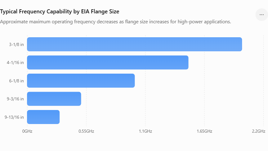
Typical Frequency Capability
Typical Frequency Capability by EIA Flange Size
Approximate maximum operating frequency decreases as flange size increases for high-power applications.
Industries That Use EIA Flange Connectors
| Industry | Purpose |
|---|---|
| Broadcasting | RF transmission |
| Telecommunications | Base station interconnection |
| Defense | Radar systems |
| Aerospace | Ground communication |
| Medical | RF generators |
| Semiconductor | Plasma equipment |
| Research Laboratories | RF testing |
| Satellite Communication | Earth stations |
How to Choose the Right EIA Flange Connector
Consider the following factors before selecting an EIA flange connector:
- Required operating frequency
- RF power level
- Transmission line size
- Indoor or outdoor installation
- Pressurized or non-pressurized system
- Environmental conditions
- Material compatibility
- Corrosion resistance
- Mechanical load
- Industry standards
Installation Best Practices
- Clean flange surfaces before installation.
- Use the correct conductive gasket.
- Tighten bolts evenly using a cross-pattern sequence.
- Follow the manufacturer’s torque recommendations.
- Inspect alignment before energizing the system.
- Test VSWR after installation.
- Periodically inspect for corrosion and loose hardware.
Maintenance Tips
- Inspect bolts regularly.
- Clean contact surfaces.
- Replace damaged gaskets.
- Check for corrosion.
- Verify pressurization in sealed systems.
- Measure insertion loss during maintenance.
- Replace worn bullet contacts when necessary.
Future Trends
As broadcasting, satellite communications, high-power RF systems, and industrial microwave applications continue to evolve, EIA flange connectors are being enhanced with lightweight materials, improved corrosion-resistant coatings, higher-frequency designs, and advanced sealing technologies. Future developments will focus on increasing power efficiency, reducing maintenance requirements, and improving performance in harsh outdoor and mission-critical environments.
Conclusion
EIA Flange Connectors are among the most reliable and efficient interconnection solutions for high-power RF and microwave transmission systems. Their standardized design, exceptional power handling capability, low insertion loss, excellent impedance matching, and rugged construction make them indispensable in broadcasting, telecommunications, defense, aerospace, satellite communication, and industrial RF applications. Choosing the correct flange size, transmission line compatibility, and environmental protection ensures long-term system reliability and maximum RF performance.
Frequently Asked Questions (FAQs)
1. What is an EIA Flange Connector?
An EIA Flange Connector is a standardized high-power RF connector used with rigid coaxial transmission lines for broadcasting, telecommunications, radar, and microwave systems.
2. What does EIA stand for?
EIA stands for Electronic Industries Alliance, the organization that established dimensional standards for these connectors.
3. Where are EIA Flange Connectors used?
They are widely used in FM and TV broadcasting, radar systems, satellite earth stations, military communications, industrial RF heating, and laboratory testing.
4. What impedance do EIA Flange Connectors use?
Most EIA flange connectors are designed with a 50 Ohm characteristic impedance.
5. What are the common EIA flange sizes?
Common sizes include 3-1/8″, 4-1/16″, 6-1/8″, 9-3/16″, and 9-13/16″.
6. What are the advantages of EIA Flange Connectors?
They provide high power handling, low insertion loss, excellent VSWR, rugged construction, long service life, and reliable RF performance.
7. Can EIA Flange Connectors be used outdoors?
Yes. Outdoor versions include weatherproof gaskets, corrosion-resistant plating, and sealed designs suitable for harsh environments.
8. What materials are used to manufacture EIA Flange Connectors?
Common materials include copper, brass, aluminum, stainless steel, silver plating, and conductive elastomer seals.
9. How do I choose the correct EIA Flange Connector?
Select one based on operating frequency, RF power, transmission line diameter, environmental conditions, and compatibility with your existing system.
10. What maintenance is required?
Routine inspection, cleaning of contact surfaces, checking bolt torque, replacing worn gaskets, and verifying VSWR help maintain reliable long-term performance.
Typical Frequency Capability by EIA Flange Size
Approximate maximum operating frequency decreases as flange size increases for high-power applications.
| size | frequency |
|---|---|
| 3-1/8 in | 2 |
| 4-1/16 in | 1.5 |
| 6-1/8 in | 1 |
| 9-3/16 in | 0.5 |
| 9-13/16 in | 0.3 |