In modern RF and microwave communication systems, accurate signal monitoring and power measurement are essential for maintaining network performance and reliability. One of the most important passive RF components used for this purpose is the Bi-Directional Coupler.
A bi-directional coupler enables engineers and network operators to simultaneously monitor forward and reverse RF power within a transmission line. It is widely used in telecommunications, broadcasting, wireless networks, satellite communication, defense systems, and RF testing applications.
This comprehensive guide explains what a bi-directional coupler is, how it works, its features, benefits, types, and applications, helping you understand its critical role in RF systems.
What is a Bi-Directional Coupler?
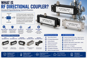
A Bi-Directional Coupler is a passive RF device designed to sample RF signals traveling in both directions along a transmission line. Unlike a standard directional coupler that measures power flowing in a single direction, a bi-directional coupler provides separate outputs for monitoring both forward and reflected signals.
The device allows a small portion of the transmitted power to be coupled and measured without significantly affecting the main signal path.
Bi-directional couplers are commonly used for:
- Power monitoring
- VSWR measurement
- Signal testing
- Network optimization
- Antenna performance analysis
- RF system protection
How Does a Bi-Directional Coupler Work?
A bi-directional coupler is installed between RF equipment such as transmitters, amplifiers, antennas, and communication systems.
Forward Power Monitoring
When RF energy travels from the transmitter toward the antenna, the coupler samples a small amount of power and directs it to the forward monitoring port.
Reflected Power Monitoring
If impedance mismatches occur within the system, part of the signal reflects back toward the transmitter. The coupler detects this reflected energy and routes it to the reverse monitoring port.
By comparing forward and reflected power, engineers can evaluate:
- Antenna efficiency
- Transmission line performance
- Return loss
- VSWR (Voltage Standing Wave Ratio)
- System health
Key Components of a Bi-Directional Coupler
Main Transmission Line
The primary path through which RF power flows.
Coupling Section
Extracts a small, controlled portion of RF energy from the transmission line.
Forward Port
Provides a sampled signal representing forward power.
Reverse Port
Provides a sampled signal representing reflected power.
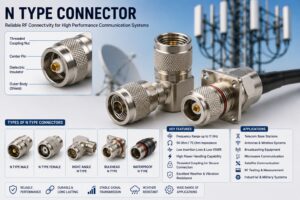
Connectors
Typically include:
- N-Type Connectors
- DIN Connectors
- SMA Connectors
- BNC Connectors
- Custom RF Interfaces
Key Features of Bi-Directional Couplers
Simultaneous Forward and Reverse Power Measurement
One of the most important features is the ability to monitor both directions of signal flow.
High Directivity
Provides excellent separation between forward and reflected signals for accurate measurements.
Low Insertion Loss
Allows RF signals to pass through with minimal attenuation.
Wide Frequency Range
Available for frequencies ranging from:
- VHF
- UHF
- GSM
- LTE
- 5G
- Microwave Bands
High Power Handling
Supports low-power testing applications as well as high-power transmission systems.
Excellent Accuracy
Ensures precise RF monitoring and diagnostics.
Compact Design
Suitable for space-constrained installations.
Technical Parameters of a Bi-Directional Coupler
Coupling Value
Defines how much power is sampled from the main line.
Typical values include:
- 3 dB
- 6 dB
- 10 dB
- 20 dB
- 30 dB
- 40 dB
Frequency Range
Determines the operating bandwidth.
Examples:
- 698–2700 MHz
- 380–3800 MHz
- 617–6000 MHz
Insertion Loss
Measures signal loss through the coupler.
Lower insertion loss indicates better efficiency.
Directivity
Represents the coupler’s ability to distinguish between forward and reflected signals.
Higher directivity ensures greater measurement accuracy.
VSWR
A low VSWR indicates good impedance matching and minimal signal reflection.
Benefits of Using a Bi-Directional Coupler
Improved Network Performance
Continuous monitoring helps maintain optimal signal transmission.
Enhanced System Protection
Detects excessive reflected power that may damage transmitters or amplifiers.
Accurate Power Measurement
Provides real-time information about RF system performance.
Simplified Maintenance
Makes troubleshooting faster and more efficient.
Reduced Downtime
Early fault detection prevents unexpected system failures.
Better Antenna Optimization
Helps engineers maximize antenna efficiency and coverage.
Types of Bi-Directional Couplers
Broadband Bi-Directional Couplers
Designed to operate across a wide frequency range.
Applications
- Multi-band networks
- DAS systems
- Cellular infrastructure
Narrowband Bi-Directional Couplers
Optimized for specific frequency bands.
Applications
- Dedicated communication systems
- Specialized RF equipment
High-Power Bi-Directional Couplers
Engineered to handle substantial RF power levels.
Applications
- Broadcast transmitters
- Base stations
- Military systems
Low-Power Bi-Directional Couplers
Used in RF laboratories and testing environments.
Applications
- Test benches
- Signal analysis
- Research facilities
Applications of Bi-Directional Couplers
Telecommunications Networks
Bi-directional couplers play a critical role in:
- Cellular base stations
- GSM networks
- LTE infrastructure
- 5G deployments
They help monitor power levels and optimize network performance.
Distributed Antenna Systems (DAS)
Used extensively in:
- Airports
- Stadiums
- Shopping malls
- Hospitals
- Commercial buildings
They assist in signal distribution and network monitoring.
Wireless Communication Systems
Applications include:
- Wi-Fi networks
- Private radio systems
- Public safety communications
Broadcasting Industry
RF broadcasters use bi-directional couplers to monitor transmitter output and antenna performance.
Applications include:
- FM radio stations
- AM broadcasting
- Television transmission systems
Satellite Communication
Used in:
- Ground stations
- VSAT systems
- Satellite uplink monitoring
Aerospace and Defense
Critical applications include:
- Radar systems
- Electronic warfare
- Military communication systems
- Aircraft communication networks
RF Testing and Measurement
Bi-directional couplers are commonly found in:
Bi-Directional Coupler vs Directional Coupler
| Feature | Bi-Directional Coupler | Directional Coupler |
|---|---|---|
| Signal Monitoring | Forward & Reverse | Single Direction |
| Reflected Power Measurement | Yes | Limited |
| VSWR Analysis | Yes | Limited |
| System Diagnostics | Advanced | Basic |
| Network Monitoring | Excellent | Moderate |
Factors to Consider When Selecting a Bi-Directional Coupler
Frequency Range
Ensure compatibility with your operating frequency.
Coupling Value
Choose the appropriate coupling level based on monitoring requirements.
Power Handling
Verify the coupler can handle the required RF power.
Connector Type
Select connectors compatible with your RF system.
Directivity
Higher directivity provides more accurate measurements.
Environmental Conditions
Consider:
- Temperature range
- Humidity
- Outdoor exposure
- Vibration resistance
Installation Best Practices
To maximize performance:
Use Quality RF Connectors
Poor connectors can introduce losses and reflections.
Maintain Proper Impedance
Ensure all components are matched to the system impedance (typically 50 Ohms).
Minimize Cable Loss
Use high-quality RF cables.
Regular Inspection
Monitor connector condition and signal performance.
Follow Manufacturer Guidelines
Proper installation ensures optimal operation and longevity.
Future of Bi-Directional Couplers in 5G and Beyond
The rapid growth of:
- 5G networks
- Private LTE
- IoT infrastructure
- Smart cities
- Satellite internet
is increasing demand for advanced RF monitoring solutions.
Modern bi-directional couplers are being designed with:
- Wider bandwidths
- Higher power handling
- Improved directivity
- Compact footprints
- Multi-band compatibility
These advancements make them essential components in next-generation communication systems.
Conclusion
A Bi-Directional Coupler is a crucial RF component that enables accurate monitoring of both forward and reflected power within communication systems. By providing real-time insight into signal performance, antenna efficiency, and system health, bi-directional couplers help optimize network operation, improve reliability, and protect valuable RF equipment.
From telecommunications and DAS installations to broadcasting, satellite communication, aerospace, defense, and RF testing, bi-directional couplers play a vital role in ensuring efficient signal transmission and network performance. As wireless technologies continue to evolve, the importance of high-quality bi-directional couplers will only continue to grow.