In modern RF (Radio Frequency), microwave, wireless communication, radar, satellite, broadcasting, aerospace, defense, and telecommunications systems, efficient signal distribution is critical for maintaining network performance and signal integrity. One of the most widely used passive RF components for signal splitting and combining is the Wilkinson Power Divider.
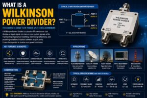
The Wilkinson Power Divider is a specialized RF power splitter designed to divide an input signal into multiple output signals while maintaining impedance matching, minimizing signal reflections, and providing excellent isolation between output ports. Unlike conventional power splitters, the Wilkinson design offers superior performance with minimal insertion loss and excellent port-to-port isolation.
Since its invention by Ernest J. Wilkinson in 1960, the Wilkinson Power Divider has become a fundamental component in RF and microwave engineering. It is commonly found in antenna systems, wireless networks, test equipment, radar systems, satellite communication networks, and 5G infrastructure.
This comprehensive guide explains what a Wilkinson Power Divider is, how it works, its construction, advantages, applications, specifications, and how to select the right model for your RF system.
What Is a Wilkinson Power Divider?
A Wilkinson Power Divider is a passive RF component that equally or unequally divides an input signal into two or more output signals while maintaining impedance matching and high isolation between output ports.
The device can also operate in reverse as a power combiner, combining multiple input signals into a single output signal.
The key objectives of a Wilkinson Power Divider are:
- Equal signal distribution
- Impedance matching
- Minimal insertion loss
- High isolation between outputs
- Low VSWR
- Excellent return loss
Because of these characteristics, Wilkinson dividers are considered one of the most efficient RF power splitting solutions available.
History of the Wilkinson Power Divider
The Wilkinson Power Divider was invented by Ernest J. Wilkinson in 1960.
Before its development, engineers often used resistive power splitters, which suffered from:
- High insertion loss
- Poor efficiency
- Limited isolation
Wilkinson introduced a design that used transmission lines and isolation resistors to create a highly efficient RF power divider with minimal losses and excellent output isolation.
Today, Wilkinson dividers remain one of the most commonly used RF passive components in microwave engineering.
How Does a Wilkinson Power Divider Work?
The Wilkinson Power Divider operates using transmission line theory and impedance matching principles.
Signal Input
An RF signal enters the input port.
Signal Division
The signal is split equally into two output transmission lines.
Quarter-Wave Transformer Sections
Each branch contains a quarter-wave transmission line that transforms impedance for proper matching.
Isolation Resistor
A resistor is connected between output ports.
This resistor:
- Improves isolation
- Reduces signal coupling
- Prevents interaction between outputs
Signal Output
The divided signals exit through the output ports with equal amplitude and phase.
The result is highly efficient power distribution with excellent RF performance.
Basic Structure of a Wilkinson Power Divider
A standard two-way Wilkinson Power Divider consists of:
Input Port
Receives the incoming RF signal.
Quarter-Wave Transmission Lines
Specially designed transmission line sections that perform impedance transformation.
Functions include:
- Impedance matching
- Power distribution
- Reflection reduction
Isolation Resistor
Typically placed between output ports.
Benefits include:
- High isolation
- Improved performance
- Reduced interaction between outputs
Output Ports
Deliver divided RF signals to connected devices.
Key Features of Wilkinson Power Dividers
Excellent Port Isolation
One of the most important advantages.
Benefits:
- Reduced interference
- Improved signal quality
- Better network performance
Low Insertion Loss
The divider minimizes power loss during signal splitting.
Advantages:
- Higher efficiency
- Improved system performance
Impedance Matching
Maintains proper impedance across all ports.
Typically:
- 50 Ohm systems
- 75 Ohm systems
Low VSWR
Provides excellent impedance matching and reduced reflections.
High Return Loss
Improves signal integrity and transmission efficiency.
Bidirectional Operation
Can function as both:
- Power Divider
- Power Combiner
Types of Wilkinson Power Dividers
Two-Way Wilkinson Power Divider
The most common configuration.
Features:
- One input
- Two outputs
Applications:
- Antenna systems
- Test equipment
- Wireless networks
Three-Way Wilkinson Power Divider
Divides signals into three equal outputs.
Used in:
- Distributed antenna systems
- RF distribution networks
Four-Way Wilkinson Power Divider
Provides four equal output signals.
Common in:
- Cellular networks
- Broadcasting systems
- Radar systems
Multi-Way Wilkinson Dividers
Available in:
- 8-way
- 16-way
- 32-way
Applications include large RF distribution systems.
Unequal Wilkinson Power Divider
Provides different power levels at each output.
Used where specific signal distribution ratios are required.
Electrical Specifications of Wilkinson Power Dividers
Specifications vary depending on design and frequency range.
Typical values include:
| Parameter | Typical Value |
|---|---|
| Impedance | 50 Ohm |
| Frequency Range | DC to 40 GHz+ |
| Insertion Loss | Low |
| Isolation | High |
| VSWR | Low |
| Return Loss | High |
| Power Handling | Application Dependent |
These characteristics make Wilkinson dividers suitable for a wide range of RF applications.
Advantages of Wilkinson Power Dividers
Superior Isolation
The isolation resistor minimizes output port interaction.
Efficient Power Distribution
Most of the input power reaches output ports.
Excellent Matching
Reduces reflections throughout the RF system.
Wide Frequency Support
Available for:
- VHF
- UHF
- Microwave
- Millimeter-wave frequencies
Reliable Performance
Provides stable operation in demanding RF environments.
Versatile Applications
Suitable for telecommunications, defense, aerospace, and testing systems.
Applications of Wilkinson Power Dividers
Telecommunications
Widely used in:
- Cellular base stations
- DAS systems
- Small cell networks
- 5G infrastructure
They distribute RF signals to multiple antennas efficiently.
Antenna Systems
Used for:
- Antenna arrays
- Beamforming systems
- Multi-antenna configurations
Satellite Communication
Applications include:
- Ground stations
- Satellite gateways
- RF distribution systems
Radar Systems
Critical for:
- Signal distribution
- Receiver networks
- Radar arrays
Aerospace and Defense
Used in:
- Electronic warfare systems
- Tactical communications
- Military radar platforms
Test and Measurement
Frequently found in:
- RF laboratories
- Calibration systems
- Network analyzer setups
Broadcasting Networks
Used for:
- RF signal distribution
- Broadcast transmitters
- Monitoring systems
Wilkinson Power Divider vs Resistive Power Divider
| Feature | Wilkinson Divider | Resistive Divider |
|---|---|---|
| Insertion Loss | Low | High |
| Isolation | Excellent | Poor |
| Efficiency | High | Moderate |
| Matching | Excellent | Good |
| Power Handling | High | Moderate |
| Complexity | Higher | Simple |
For professional RF systems, Wilkinson dividers are generally preferred.
Wilkinson Power Divider vs Hybrid Coupler
| Feature | Wilkinson Divider | Hybrid Coupler |
|---|---|---|
| Signal Split | Equal | Equal |
| Isolation | Excellent | Excellent |
| Phase Difference | Same Phase | 90° or 180° |
| Complexity | Moderate | Higher |
| Applications | General RF Distribution | Specialized RF Systems |
Frequency Ranges of Wilkinson Power Dividers
Modern Wilkinson Power Dividers are available for frequencies including:
VHF
30 MHz to 300 MHz
UHF
300 MHz to 3 GHz
Microwave
3 GHz to 30 GHz
Millimeter Wave
30 GHz to 110 GHz+
This makes them suitable for virtually every RF application.
How to Choose the Right Wilkinson Power Divider
Determine Frequency Range
Select a divider that covers the required operating frequency.
Examples:
- 700 MHz to 2700 MHz
- 2 GHz to 18 GHz
- 18 GHz to 40 GHz
Evaluate Number of Outputs
Options include:
- 2-way
- 3-way
- 4-way
- 8-way
- 16-way
Consider Power Handling
Ensure compatibility with RF power levels.
Check Isolation Requirements
Higher isolation improves network performance.
Review Connector Types
Common options include:
- SMA
- N-Type
- TNC
- 2.92 mm
Installation Best Practices
Minimize Cable Losses
Use low-loss RF cables whenever possible.
Maintain Proper Impedance
Ensure all connected devices use matching impedance.
Verify Connector Quality
High-quality RF connectors improve overall system performance.
Test Performance After Installation
Measure:
- VSWR
- Return loss
- Isolation
- Insertion loss
Protect Outdoor Installations
Use weatherproof enclosures where necessary.
Future Trends in Wilkinson Power Divider Technology
Expansion of 5G Networks
Massive MIMO systems require advanced RF signal distribution.
Satellite Communication Growth
New satellite constellations increase demand for microwave components.
Phased Array Antennas
Modern antenna systems rely heavily on power dividers.
Millimeter-Wave Technology
Increasing frequencies require precision RF components.
Defense Modernization
Advanced radar and communication systems continue driving demand.
Key Takeaways
- Wilkinson Power Dividers split RF signals efficiently.
- Provide excellent output port isolation.
- Maintain impedance matching.
- Offer low insertion loss.
- Can function as power combiners.
- Used extensively in telecom, radar, satellite, and testing applications.
- Available in multiple output configurations.
- Support frequencies from MHz to millimeter-wave bands.
Conclusion
The Wilkinson Power Divider remains one of the most important passive components in RF and microwave engineering. Its unique ability to split power efficiently while maintaining impedance matching and excellent output isolation makes it a preferred solution for modern communication systems.
Whether used in telecommunications, antenna arrays, radar systems, satellite communications, aerospace platforms, broadcasting networks, or RF laboratories, Wilkinson Power Dividers provide the performance, reliability, and efficiency required for today’s advanced wireless infrastructure.
As technologies such as 5G, phased-array antennas, satellite internet, and millimeter-wave communication continue to evolve, Wilkinson Power Dividers will remain a critical building block in next-generation RF system design.
FAQ About Wilkinson Power Dividers
What is a Wilkinson Power Divider used for?
It is used to split an RF signal into multiple outputs while maintaining impedance matching and output isolation.
Can a Wilkinson Divider be used as a combiner?
Yes. It can operate as both a power divider and a power combiner.
Why is output isolation important?
Isolation prevents signals from one output port affecting another, improving overall system performance.
What impedance do Wilkinson Dividers use?
Most are designed for 50-ohm RF systems, although 75-ohm versions are also available.
Where are Wilkinson Power Dividers commonly used?
Telecommunications, radar systems, satellite communication, broadcasting, aerospace, defense, and RF testing.