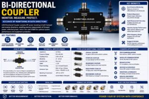
A Bi-Directional Coupler is an essential passive RF and microwave component used to monitor, sample, and measure radio frequency signals traveling in both forward and reverse directions within a transmission line. Unlike a conventional directional coupler that samples RF power flowing in only one direction, a bi-directional coupler simultaneously measures both forward and reflected power, making it indispensable in modern communication, broadcasting, radar, satellite, and wireless systems.
As RF communication technologies evolve toward higher frequencies and greater power levels, maintaining signal quality and system efficiency has become increasingly important. Bi-Directional Couplers help engineers monitor signal transmission, identify impedance mismatches, detect reflected power, and protect expensive RF equipment from damage caused by excessive reflections.
These couplers are widely used in 5G networks, satellite communication, military communication, broadcasting stations, RF testing laboratories, industrial automation, aerospace, medical electronics, and research institutions. Their ability to provide accurate power monitoring while introducing minimal insertion loss makes them one of the most important passive components in RF engineering.
This comprehensive guide explains everything about Bi-Directional Couplers, including their working principle, construction, specifications, types, applications, advantages, and selection criteria.
What Is a Bi-Directional Coupler?
A Bi-Directional Coupler is a passive microwave device designed to sample RF power traveling in both forward and reverse directions along a transmission line without significantly affecting the primary signal.
The coupler has multiple ports that allow engineers to measure transmitted power, reflected power, insertion loss, and Voltage Standing Wave Ratio (VSWR) simultaneously.
Because it continuously monitors both signal directions, a bi-directional coupler provides valuable diagnostic information for maintaining RF system performance and preventing equipment failures.
How Does a Bi-Directional Coupler Work?
A Bi-Directional Coupler works by extracting a small, predetermined portion of the RF signal from the main transmission line.
When RF energy travels toward the load, a small amount of forward power is coupled to one monitoring port.
If impedance mismatch causes signal reflections, the reflected RF energy travels back toward the transmitter. The coupler samples this reflected signal through another monitoring port.
This dual sampling capability enables engineers to calculate:
- Forward power
- Reflected power
- Return loss
- VSWR
- Transmission efficiency
The majority of the RF power continues toward the load with minimal insertion loss.
Construction of a Bi-Directional Coupler
Main Transmission Line
The primary RF signal passes through the main transmission path with minimal attenuation.
Coupling Section
The coupling section extracts a small percentage of RF energy for measurement purposes.
Common coupling methods include:
- Stripline
- Microstrip
- Waveguide
- Coaxial coupling
Coupled Ports
Separate ports provide access to:
- Forward power
- Reverse power
Connector Interfaces
Common connector types include:
- SMA
- N-Type
- BNC
- TNC
- 7/16 DIN
- 4.3-10
- 2.92 mm
- 2.4 mm
Housing
The housing provides mechanical protection and electromagnetic shielding.
Typical materials include:
- Aluminum alloy
- Brass
- Stainless steel
Key Features of Bi-Directional Couplers
- Simultaneous forward and reverse power measurement
- Low insertion loss
- Excellent directivity
- High isolation
- Wide frequency range
- Accurate RF monitoring
- Stable impedance
- Compact design
- High power handling
- Excellent repeatability
- Reliable long-term performance
- Easy system integration
Technical Specifications
| Specification | Typical Value |
| Characteristic Impedance | 50 Ohms |
| Frequency Range | DC to 40 GHz (model dependent) |
| Coupling Value | 3 dB to 40 dB |
| Directivity | 20–40 dB |
| Insertion Loss | Very Low |
| VSWR | ≤ 1.20 |
| Connector Types | SMA, N-Type, 2.92 mm, 2.4 mm |
| Power Handling | Up to Several Kilowatts |
| Operating Temperature | -40°C to +85°C |
| Construction | Coaxial, Stripline, Waveguide |
Types of Bi-Directional Couplers
Coaxial Bi-Directional Coupler
Designed for coaxial RF communication systems.
Commonly used in:
- Cellular networks
- Broadcasting
- Satellite communication
Stripline Coupler
Manufactured using printed circuit technology.
Suitable for:
- RF modules
- Wireless devices
- Microwave circuits
Waveguide Coupler
Designed for extremely high-frequency microwave systems.
Applications include:
- Radar
- Aerospace
- Satellite systems
High-Power Coupler
Designed for transmitter monitoring in high-power RF systems.
Broadband Coupler
Supports a very wide operating frequency range for laboratory and communication applications.
Common Coupling Values
Bi-Directional Couplers are available with various coupling levels, including:
- 3 dB
- 6 dB
- 10 dB
- 15 dB
- 20 dB
- 30 dB
- 40 dB
Lower coupling values sample more RF power, while higher values extract smaller signal levels.
Applications of Bi-Directional Couplers
Telecommunications
Used in cellular base stations and wireless communication infrastructure.
5G Networks
Supports RF monitoring, beamforming systems, and antenna testing.
Broadcasting
Measures transmitter output power and reflected signals.
Satellite Communication
Monitors uplink and downlink microwave transmission systems.
Aerospace
Supports aircraft communication and navigation systems.
Defense
Used in radar systems, military communication, and electronic warfare.
RF Test Laboratories
Used with spectrum analyzers, network analyzers, signal generators, and power meters.
Industrial Automation
Monitors wireless communication systems in manufacturing facilities.
Medical Equipment
Supports microwave imaging and RF diagnostic systems.
Scientific Research
Used in universities and advanced microwave research laboratories.
Advantages of Bi-Directional Couplers
- Simultaneous forward and reflected power measurement
- Improved system diagnostics
- Low insertion loss
- High measurement accuracy
- Excellent directivity
- Reliable RF monitoring
- Enhanced equipment protection
- Stable electrical performance
- Long operational life
- Wide frequency compatibility
- High power handling capability
- Easy installation
Limitations of Bi-Directional Couplers
- Higher cost than simple directional couplers
- Precision installation required
- Performance varies with frequency
- Connector quality affects measurement accuracy
- High-frequency models require careful handling
How to Choose the Right Bi-Directional Coupler
Selecting the appropriate coupler depends on several engineering factors.
- Operating frequency
- Coupling value
- Power handling
- Directivity
- Insertion loss
- Connector type
- Impedance
- Environmental conditions
- Measurement accuracy
- Installation requirements
Bi-Directional Coupler vs Directional Coupler
| Feature | Bi-Directional Coupler | Directional Coupler |
| Power Measurement | Forward & Reverse | Single Direction |
| Reflected Power Detection | Yes | Limited |
| VSWR Measurement | Yes | Requires Additional Components |
| RF Monitoring | Comprehensive | Basic |
| Applications | Advanced RF Systems | General RF Systems |
| Cost | Higher | Lower |
Industries Using Bi-Directional Couplers
Bi-Directional Couplers are widely used in:
- Telecommunications
- Broadcasting
- Aerospace
- Defense
- Satellite Communication
- Medical Electronics
- Semiconductor Manufacturing
- Scientific Research
- Industrial Automation
- RF Test Laboratories
Maintenance Tips
To maximize coupler performance:
- Keep RF connectors clean.
- Avoid exceeding rated power.
- Inspect connectors periodically.
- Use proper installation torque.
- Protect unused ports with termination loads.
- Store in dry environments.
- Calibrate measurement systems regularly.
Future Trends of Bi-Directional Couplers
The growing adoption of 5G Advanced, 6G, satellite internet, autonomous vehicles, smart manufacturing, and advanced defense systems is driving demand for highly accurate RF monitoring solutions. Future Bi-Directional Couplers will feature wider frequency coverage, lower insertion loss, higher directivity, improved thermal management, and compact designs optimized for millimeter-wave communication. Advances in precision manufacturing and new materials will enable couplers to operate efficiently beyond 100 GHz while supporting AI-driven network monitoring and next-generation wireless technologies.
Conclusion
Bi-Directional Couplers are critical passive RF components that enable accurate monitoring of forward and reflected power in high-frequency communication systems. Their ability to measure signal transmission in both directions helps engineers optimize system efficiency, detect impedance mismatches, reduce signal reflections, and protect expensive RF equipment. From telecommunications and satellite communication to aerospace, defense, medical electronics, and laboratory testing, Bi-Directional Couplers play an essential role in ensuring reliable, high-performance RF system operation.
Frequently Asked Questions (FAQs)
1. What is a Bi-Directional Coupler?
A Bi-Directional Coupler is a passive RF device that samples both forward and reflected RF power without significantly affecting the main transmission signal.
2. What is the purpose of a Bi-Directional Coupler?
Its primary purpose is to monitor forward power, reflected power, return loss, and VSWR while helping protect RF equipment and improve system performance.
3. How does a Bi-Directional Coupler work?
It extracts a small portion of the RF signal traveling in both forward and reverse directions through separate coupled ports for measurement and analysis.
4. What is the difference between a Bi-Directional Coupler and a Directional Coupler?
A Bi-Directional Coupler measures both forward and reflected power simultaneously, whereas a standard Directional Coupler typically measures power in only one direction.
5. What frequency range do Bi-Directional Couplers support?
Depending on the design, they can operate from DC up to 40 GHz or higher in specialized microwave applications.
6. Where are Bi-Directional Couplers used?
They are widely used in telecommunications, 5G infrastructure, broadcasting, satellite communication, aerospace, defense, industrial automation, and RF testing laboratories.
7. What connector types are available for Bi-Directional Couplers?
Common connector options include SMA, N-Type, BNC, TNC, 2.92 mm, 2.4 mm, 7/16 DIN, and 4.3-10 connectors.
8. What are the advantages of a Bi-Directional Coupler?
They provide accurate RF monitoring, low insertion loss, excellent directivity, high power handling, improved diagnostics, and enhanced equipment protection.
9. How do I choose the right Bi-Directional Coupler?
Choose a coupler based on operating frequency, coupling value, power handling, directivity, insertion loss, connector type, impedance, and environmental requirements.
10. Can Bi-Directional Couplers be used in 5G systems?
Yes. They are widely used in 5G base stations, antenna systems, RF testing, beamforming networks, and wireless infrastructure to monitor signal quality and optimize network performance.