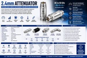
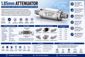
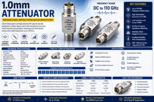
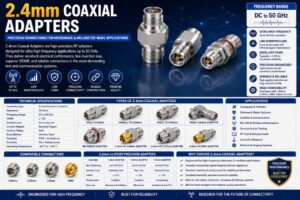
As microwave and millimeter-wave communication systems continue to evolve, maintaining precise signal levels has become essential for achieving reliable performance. One of the most important passive components used for signal control in high-frequency applications is the 1.85mm Attenuator. Designed specifically for frequencies up to 67 GHz, these precision attenuators are widely used in aerospace, defense, satellite communication, semiconductor testing, RF laboratories, 5G and 6G research, radar systems, and advanced microwave communication networks.
A 1.85mm Attenuator reduces RF signal power by a predetermined amount while preserving signal quality, impedance matching, and frequency response. Unlike amplifiers, which increase signal strength, attenuators intentionally reduce signal levels to protect sensitive equipment, improve measurement accuracy, prevent receiver overload, and optimize system performance.
These attenuators are manufactured using high-precision resistor networks and premium microwave connectors to ensure extremely low VSWR, excellent return loss, and minimal insertion loss beyond the specified attenuation value.
This comprehensive guide explains everything about 1.85mm Attenuators, including their construction, working principle, specifications, applications, advantages, limitations, and selection criteria.
What Is a 1.85mm Attenuator?
A 1.85mm Attenuator is a precision RF and microwave passive component that reduces signal power by a fixed attenuation value while maintaining a constant 50 Ohm impedance throughout the transmission path.
It is equipped with 1.85mm (V Connector) interfaces that support microwave and millimeter-wave frequencies up to 67 GHz, making it ideal for advanced communication and measurement systems.
The attenuation value remains constant throughout operation, ensuring stable and repeatable performance across the specified frequency range.
How Does a 1.85mm Attenuator Work?
A 1.85mm Attenuator works by converting part of the incoming RF signal energy into heat using an internal precision resistor network.
The remaining signal passes through the attenuator to the output connector with reduced power while maintaining excellent impedance matching.
Its precision design minimizes reflections, preserves waveform integrity, and maintains consistent attenuation across the entire operating frequency range.
Because no external power source is required, the attenuator operates as a completely passive RF component.
Construction of a 1.85mm Attenuator
1.85mm Connectors
The attenuator features precision 1.85mm microwave connectors.
These connectors provide:
- Excellent impedance matching
- Low VSWR
- High-frequency compatibility
- Secure threaded coupling
Internal Resistive Network
The attenuation is achieved using precision thin-film or thick-film resistor networks designed for microwave frequencies.
These networks ensure:
- Stable attenuation
- Excellent repeatability
- Low signal distortion
Center Contact
The center conductor transfers RF energy.
Common materials include:
- Beryllium Copper
- Gold-Plated Copper Alloy
Dielectric
The dielectric maintains conductor spacing.
Common materials include:
- PTFE
- Air dielectric
- High-performance engineering polymers
Housing
The housing provides shielding and mechanical strength.
Typical materials include:
- Stainless Steel
- Passivated Stainless Steel
Key Features of 1.85mm Attenuators
- Supports frequencies up to 67 GHz
- Precision microwave performance
- Low insertion loss
- Excellent return loss
- Low VSWR
- Stable attenuation values
- Precision 50 Ohm impedance
- Gold-plated contacts
- Stainless steel construction
- Excellent repeatability
- Long operational life
- Rugged mechanical design
Technical Specifications
| Specification | Typical Value |
| Connector Type | 1.85mm (V Connector) |
| Characteristic Impedance | 50 Ohms |
| Frequency Range | DC to 67 GHz |
| Attenuation Values | 1 dB to 60 dB |
| VSWR | ≤ 1.20 |
| Insertion Loss | Very Low |
| Power Rating | 1 W to 20 W (Model Dependent) |
| Contact Material | Beryllium Copper |
| Contact Plating | Gold |
| Body Material | Stainless Steel |
| Operating Temperature | -55°C to +125°C |
Common Attenuation Values
Standard attenuation values include:
- 1 dB
- 2 dB
- 3 dB
- 5 dB
- 6 dB
- 10 dB
- 15 dB
- 20 dB
- 30 dB
- 40 dB
- 50 dB
- 60 dB
Types of 1.85mm Attenuators
Fixed Attenuator
Provides a constant attenuation value throughout operation.
High-Power Attenuator
Designed for applications requiring higher RF power handling.
Precision Laboratory Attenuator
Optimized for measurement accuracy in RF test systems.
Broadband Attenuator
Maintains consistent performance across a wide frequency range.
Low VSWR Attenuator
Designed for applications requiring minimal signal reflections.
Applications of 1.85mm Attenuators
RF Test Laboratories
Used in vector network analyzers, spectrum analyzers, and calibration systems.
Aerospace
Supports aircraft communication systems and microwave avionics testing.
Defense
Used in radar systems, electronic warfare, missile guidance, and military communication equipment.
Satellite Communication
Provides precise signal control in satellite payload testing and ground stations.
Semiconductor Testing
Supports wafer probing, integrated circuit characterization, and high-frequency device measurements.
5G and 6G Development
Used in millimeter-wave communication testing and base station development.
Medical Electronics
Applied in microwave diagnostic equipment and imaging systems.
Scientific Research
Used in universities, research laboratories, and government institutions for advanced RF experiments.
Advantages of 1.85mm Attenuators
- Supports frequencies up to 67 GHz
- Excellent signal integrity
- Low insertion loss
- Outstanding impedance stability
- Precision attenuation accuracy
- Superior return loss
- Reliable measurement performance
- Compact design
- Long service life
- Excellent mechanical durability
- Corrosion-resistant construction
- Suitable for millimeter-wave systems
Limitations of 1.85mm Attenuators
- Higher cost than standard RF attenuators
- Requires careful connector handling
- Limited flexibility due to fixed attenuation values
- Sensitive precision connectors require proper maintenance
- Proper installation torque is essential
How to Choose the Right 1.85mm Attenuator
When selecting a 1.85mm Attenuator, consider:
- Operating frequency
- Required attenuation value
- Power handling capacity
- Connector compatibility
- VSWR requirements
- Insertion loss
- Environmental conditions
- Laboratory or field application
- Mechanical durability
- Manufacturer quality certifications
1.85mm Attenuator vs 2.92mm Attenuator
| Feature | 1.85mm Attenuator | 2.92mm Attenuator |
| Maximum Frequency | Up to 67 GHz | Up to 40 GHz |
| Connector Type | 1.85mm (V) | 2.92mm (K) |
| Microwave Performance | Excellent | Excellent |
| Millimeter-Wave Capability | Superior | Very Good |
| Laboratory Applications | Advanced | Standard Precision |
| Cost | Higher | Moderate |
| Precision | Ultra High | Very High |
| Typical Applications | 6G, Radar, Research | 5G, RF Testing |
Industries Using 1.85mm Attenuators
1.85mm Attenuators are widely used in:
- Telecommunications
- Aerospace
- Defense
- Satellite Communication
- Semiconductor Manufacturing
- Scientific Research
- Medical Electronics
- Microwave Engineering
- RF Test Laboratories
- Advanced Wireless Development
Maintenance Tips
To maximize attenuator performance:
- Keep connector interfaces clean.
- Use protective dust caps.
- Avoid excessive mating cycles.
- Apply recommended connector torque.
- Store in dry environments.
- Inspect connectors regularly.
- Replace damaged components immediately.
Future Trends of 1.85mm Attenuators
As communication technologies continue advancing toward 6G, terahertz communication, advanced radar, satellite internet, and ultra-high-speed semiconductor testing, the demand for precision microwave attenuators will continue to grow. Manufacturers are developing next-generation 1.85mm attenuators with improved thermal stability, lower insertion loss, enhanced power handling, advanced thin-film resistor technology, and superior frequency performance beyond 67 GHz. These innovations will support the increasingly demanding requirements of future RF and millimeter-wave communication systems.
Conclusion
1.85mm Attenuators are among the most advanced RF signal control components used in microwave and millimeter-wave applications. Their ability to provide accurate signal attenuation while maintaining exceptional impedance stability, low VSWR, minimal insertion loss, and reliable performance up to 67 GHz makes them indispensable in aerospace, defense, satellite communication, semiconductor testing, medical electronics, scientific research, and next-generation wireless technologies. Selecting the correct attenuation value, power rating, and connector configuration ensures long-term reliability and optimal RF system performance.
Frequently Asked Questions (FAQs)
1. What is a 1.85mm Attenuator?
A 1.85mm Attenuator is a precision RF passive component that reduces microwave signal power by a fixed amount while maintaining excellent signal integrity up to 67 GHz.
2. What frequency does a 1.85mm Attenuator support?
Most 1.85mm Attenuators support frequencies from DC to 67 GHz, depending on the model and manufacturer.
3. What connector does a 1.85mm Attenuator use?
It uses precision 1.85mm (V Connector) interfaces designed for high-frequency microwave and millimeter-wave applications.
4. What attenuation values are available?
Common attenuation values include 1 dB, 2 dB, 3 dB, 5 dB, 6 dB, 10 dB, 15 dB, 20 dB, 30 dB, 40 dB, 50 dB, and 60 dB.
5. What impedance does a 1.85mm Attenuator have?
Standard 1.85mm Attenuators are designed with a 50 Ohm characteristic impedance.
6. Where are 1.85mm Attenuators used?
They are used in aerospace, defense, satellite communication, RF laboratories, semiconductor testing, 5G and 6G development, medical electronics, and scientific research.
7. What are the advantages of a 1.85mm Attenuator?
They provide extremely low insertion loss, excellent VSWR, precise attenuation, stable impedance, high-frequency capability, and reliable microwave performance.
8. Can a 1.85mm Attenuator handle high RF power?
Yes. Depending on the model, power ratings typically range from 1 Watt to 20 Watts, with specialized versions supporting higher power levels.
9. How do I choose the right 1.85mm Attenuator?
Choose based on operating frequency, attenuation value, power rating, connector compatibility, VSWR, insertion loss, and application requirements.
10. How should a 1.85mm Attenuator be maintained?
Keep connectors clean, use protective caps, avoid contamination, apply proper mating torque, inspect interfaces regularly, and store the attenuator in a clean, dry environment.