
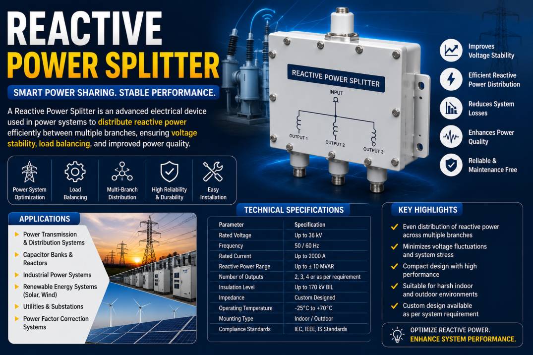
A Reactive Power Splitter is an essential passive RF and microwave component used to divide or combine radio frequency signals while minimizing power loss and maintaining signal integrity. Unlike resistive power splitters that dissipate energy through resistors, reactive power splitters utilize reactive components such as transformers, transmission lines, capacitors, and inductors to distribute RF power efficiently. This design enables lower insertion loss, improved efficiency, and better overall performance in high-frequency communication systems.
Reactive power splitters are widely used in wireless communication, satellite communication, radar systems, aerospace, defense, laboratory testing, broadcasting, and modern 4G/5G networks. Their ability to divide an input signal into two or more output signals with minimal loss makes them a critical component in RF distribution networks, antenna systems, measurement equipment, and signal processing applications.
As communication technologies continue to evolve toward higher frequencies and greater bandwidths, reactive power splitters have become indispensable for ensuring reliable signal transmission, balanced power distribution, and excellent impedance matching across RF systems.
This comprehensive guide explains everything about Reactive Power Splitters, including their working principle, construction, specifications, types, applications, advantages, limitations, and selection criteria.
What Is a Reactive Power Splitter?
A Reactive Power Splitter is a passive microwave device designed to divide one RF input signal into multiple output signals or combine multiple RF signals into a single output while maintaining minimal insertion loss and proper impedance matching.
Unlike resistive splitters, which convert part of the RF energy into heat, reactive power splitters rely on carefully designed transmission lines, transformers, inductive elements, and capacitive networks to transfer power efficiently.
The result is improved efficiency, reduced signal attenuation, lower heat generation, and higher power handling capability, making reactive power splitters ideal for high-performance RF and microwave applications.
How Does a Reactive Power Splitter Work?
A Reactive Power Splitter works by distributing RF energy through reactive circuit elements rather than resistive components.
When an RF signal enters the input port, the internal transmission line network divides the signal equally or unequally among the output ports while maintaining the desired impedance.
Because the internal components store and transfer energy instead of dissipating it as heat, the splitter achieves very low insertion loss and excellent signal efficiency.
Proper impedance matching ensures that signal reflections are minimized, resulting in improved return loss, lower VSWR, and enhanced transmission quality.
Construction of a Reactive Power Splitter
A Reactive Power Splitter consists of several precision-engineered components.
Input Port
Receives the incoming RF signal from the transmitter or source.
Output Ports
Deliver divided RF signals to antennas, receivers, amplifiers, or other RF devices.
Transmission Line Network
Microstrip or stripline transmission paths distribute RF power efficiently.
Reactive Components
Depending on the design, the splitter may include:
- Inductors
- Capacitors
- RF transformers
- Quarter-wave transmission lines
Housing
The housing is typically manufactured from aluminum, brass, or stainless steel to provide mechanical strength and electromagnetic shielding.
RF Connectors
Common connector options include:
- SMA
- N-Type
- BNC
- TNC
- 2.92 mm
- 2.4 mm
- SMP
- SMPM
- 7/16 DIN
- 4.3-10
Working Principle
Reactive Power Splitters are based on electromagnetic coupling and impedance transformation.
The incoming RF signal travels through specially designed transmission line sections that divide energy equally or according to a specified ratio.
Unlike resistive circuits, reactive networks temporarily store electromagnetic energy and transfer it to the output ports without significant power dissipation.
This process results in:
- Low insertion loss
- High efficiency
- Excellent isolation
- Stable phase response
- Wide operating bandwidth
Types of Reactive Power Splitters
Wilkinson Power Splitter
The Wilkinson Power Splitter is one of the most widely used reactive power splitters.
Features include:
- Excellent isolation
- Low insertion loss
- Equal power division
- High return loss
- Good impedance matching
Hybrid Power Splitter
Hybrid splitters divide RF signals while maintaining specific phase relationships.
Applications include:
- Balanced amplifiers
- RF mixers
- Radar systems
Unequal Power Splitter
Designed to divide RF power in specified ratios such as:
- 2:1
- 3:1
- 4:1
Commonly used in specialized RF networks.
Multi-Way Reactive Splitters
Available in:
- 2-Way
- 3-Way
- 4-Way
- 6-Way
- 8-Way
- 16-Way
These devices distribute RF signals to multiple outputs.
Technical Specifications
| Specification | Typical Value |
| Frequency Range | DC to 67 GHz |
| Characteristic Impedance | 50 Ohms |
| Insertion Loss | Very Low |
| Return Loss | >20 dB |
| Isolation | >20 dB |
| VSWR | <1.25 |
| Power Handling | Up to Hundreds of Watts |
| Connector Types | SMA, N, TNC, 2.92 mm |
| Operating Temperature | -55°C to +85°C |
Common Frequency Ranges
Reactive Power Splitters are available for numerous RF bands.
Typical frequency ranges include:
- DC to 1 GHz
- DC to 3 GHz
- DC to 6 GHz
- DC to 12 GHz
- DC to 18 GHz
- DC to 26.5 GHz
- DC to 40 GHz
- DC to 50 GHz
- DC to 67 GHz
Specialized microwave models can support frequencies above 100 GHz.
Applications of Reactive Power Splitters
Wireless Communication
- Cellular base stations
- 4G networks
- 5G infrastructure
- Small cells
Satellite Communication
- Ground stations
- VSAT systems
- Satellite receivers
- Satellite transmitters
Radar Systems
- Air traffic radar
- Marine radar
- Military radar
- Weather radar
Aerospace and Defense
- Electronic warfare
- Aircraft communication
- Missile guidance
- Navigation systems
Broadcasting
- Television transmission
- FM radio
- Digital broadcasting
RF Laboratories
- Signal generators
- Spectrum analyzers
- Network analyzers
- Calibration systems
Medical Equipment
- MRI systems
- RF diagnostic instruments
- Medical imaging equipment
Industrial Automation
- Wireless sensors
- Industrial communication
- Remote monitoring
- Factory automation
Advantages of Reactive Power Splitters
- Very low insertion loss
- High power efficiency
- Excellent impedance matching
- Superior isolation
- Low VSWR
- High power handling capability
- Minimal heat generation
- Wide frequency range
- Excellent signal integrity
- Long operational life
- Reliable performance
- Compact design
Limitations of Reactive Power Splitters
- More complex design than resistive splitters
- Narrower bandwidth for some configurations
- Higher manufacturing cost
- Precision fabrication required
- Performance depends on impedance matching
Reactive vs Resistive Power Splitter
| Feature | Reactive Power Splitter | Resistive Power Splitter |
| Efficiency | High | Lower |
| Insertion Loss | Low | High |
| Heat Generation | Very Low | Higher |
| Power Dissipation | Minimal | Significant |
| Isolation | Better | Moderate |
| High Power Handling | Excellent | Limited |
| Cost | Higher | Lower |
How to Choose the Right Reactive Power Splitter
When selecting a Reactive Power Splitter, consider the following factors:
- Frequency range
- Number of output ports
- Power handling
- Insertion loss
- Return loss
- Isolation
- Connector type
- Impedance
- VSWR
- Operating environment
Selecting the correct specifications ensures maximum system efficiency and reliable RF performance.
Future Trends in Reactive Power Splitters
The growing adoption of 5G, satellite internet, autonomous systems, aerospace communication, and millimeter-wave technologies is driving innovation in Reactive Power Splitters. Manufacturers are developing compact, ultra-wideband, high-power, and low-loss designs capable of operating beyond 100 GHz. Improvements in materials, precision manufacturing, and RF simulation are enabling splitters with better isolation, lower insertion loss, and enhanced thermal performance for next-generation communication systems.
Conclusion
Reactive Power Splitters are indispensable components in modern RF and microwave systems. Their ability to divide RF signals efficiently while maintaining low insertion loss, excellent impedance matching, and superior isolation makes them ideal for telecommunications, aerospace, defense, satellite communication, broadcasting, industrial automation, and laboratory testing. By choosing the correct frequency range, power rating, connector type, and output configuration, engineers can optimize system performance and ensure reliable signal distribution across complex RF networks.
Frequently Asked Questions (FAQs)
1. What is a Reactive Power Splitter?
A Reactive Power Splitter is a passive RF device that divides or combines radio frequency signals using reactive components such as transmission lines and transformers with minimal power loss.
2. How does a Reactive Power Splitter work?
It distributes RF power through reactive networks that transfer energy efficiently while maintaining impedance matching and minimizing insertion loss.
3. What is the difference between a reactive and resistive power splitter?
Reactive power splitters offer lower insertion loss, higher efficiency, and better power handling, whereas resistive splitters dissipate more energy as heat.
4. Where are Reactive Power Splitters used?
They are used in 4G/5G networks, satellite communication, radar systems, aerospace, defense, RF laboratories, broadcasting, medical equipment, and industrial automation.
5. What is the most common type of Reactive Power Splitter?
The Wilkinson Power Splitter is the most widely used due to its excellent isolation, low insertion loss, and impedance matching.
6. What connector types are available?
Reactive Power Splitters are commonly available with SMA, N-Type, TNC, BNC, 2.92 mm, 2.4 mm, SMP, and SMPM connectors.
7. What impedance is commonly used?
Most Reactive Power Splitters are designed with a standard characteristic impedance of 50 Ohms for RF and microwave systems.
8. Can Reactive Power Splitters handle high power?
Yes. Many models are designed to handle high RF power levels while maintaining low insertion loss and stable performance.
9. How do I choose the right Reactive Power Splitter?
Consider the operating frequency, number of output ports, insertion loss, isolation, power handling, connector type, impedance, and environmental requirements.
10. Why are Reactive Power Splitters preferred in RF systems?
They provide efficient power distribution, low signal loss, excellent impedance matching, superior isolation, and reliable performance in high-frequency communication systems.










